
Product Guide
Page 6
Intel Desktop Board DZ68BC Product Guide 2 Installing and Replacing Desktop Board Components Before You Begin 31 Installation ... Cards 46 Connecting SATA Cables 48 Connecting to the Internal Headers and Connectors 49 Front Panel Intel HD Audio Header 50 S/PDIF Header 50 IEEE 1394a Header 50 Chassis Intrusion Header 51 Consumer IR (CIR) Headers... 51 Front Panel Header 52 Alternate Front Panel Power LED Header 52 Serial Header 53 USB 2.0 Headers 53 USB 3.0 Connector 54 Connecting to the Audio...
Intel Desktop Board DZ68BC Product Guide 2 Installing and Replacing Desktop Board Components Before You Begin 31 Installation ... Cards 46 Connecting SATA Cables 48 Connecting to the Internal Headers and Connectors 49 Front Panel Intel HD Audio Header 50 S/PDIF Header 50 IEEE 1394a Header 50 Chassis Intrusion Header 51 Consumer IR (CIR) Headers... 51 Front Panel Header 52 Alternate Front Panel Power LED Header 52 Serial Header 53 USB 2.0 Headers 53 USB 3.0 Connector 54 Connecting to the Audio...
Product Guide
Page 8
...) Header Signal Names 52 12. EMC Regulations 83 24. Back Panel Audio Connectors 55 26. Regulatory Compliance Marks 86 viii Intel Desktop Board DZ68BC Product Guide 25. Location of the Chassis Fan Headers 56 27. Installing the WiFi/Bluetooth Module 66 31. Front Panel Intel HD Audio Header Signal Names 50 7. IEEE 1394a Header Signal...
...) Header Signal Names 52 12. EMC Regulations 83 24. Back Panel Audio Connectors 55 26. Regulatory Compliance Marks 86 viii Intel Desktop Board DZ68BC Product Guide 25. Location of the Chassis Fan Headers 56 27. Installing the WiFi/Bluetooth Module 66 31. Front Panel Intel HD Audio Header Signal Names 50 7. IEEE 1394a Header Signal...
Product Guide
Page 9
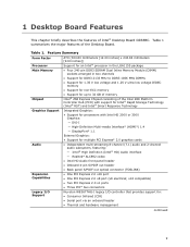
... featuring: ― Intel® High Definition (Intel® HD) Audio interface ― Realtek* ALC892 codec • Intel HD Audio front panel header • Onboard 4-pin S/PDIF out header • Back panel S/PDIF out optical ...connector (TOSLINK) • One PCI Express 2.0 x16 port • One PCI Express 2.0 x8 port (x8 electrical; Table 1 summarizes the major features of Intel® Desktop Board DZ68BC...
... featuring: ― Intel® High Definition (Intel® HD) Audio interface ― Realtek* ALC892 codec • Intel HD Audio front panel header • Onboard 4-pin S/PDIF out header • Back panel S/PDIF out optical ...connector (TOSLINK) • One PCI Express 2.0 x16 port • One PCI Express 2.0 x8 port (x8 electrical; Table 1 summarizes the major features of Intel® Desktop Board DZ68BC...
Product Guide
Page 10
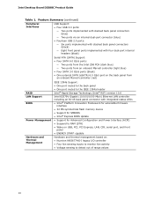
...Intel Desktop Board DZ68BC Product Guide Table 1. Feature Summary (continued) Peripheral Interfaces USB Support: • Four USB 3.0 ports: ― Two ports implemented with stacked back panel connectors (blue) ― Two ports via an internal dual-port connector (blue) • Fourteen USB 2.0 ports: ― Six ports implemented with stacked back panel...1394a Support: • One port routed to the back panel • One port routed to the IEEE 1394a header Intel® Rapid Storage Technology (Intel® RST) version 10.6 Intel 82579V Gigabit (10/100/1000 Mb/s) Ethernet LAN controller ...
...Intel Desktop Board DZ68BC Product Guide Table 1. Feature Summary (continued) Peripheral Interfaces USB Support: • Four USB 3.0 ports: ― Two ports implemented with stacked back panel connectors (blue) ― Two ports via an internal dual-port connector (blue) • Fourteen USB 2.0 ports: ― Six ports implemented with stacked back panel...1394a Support: • One port routed to the back panel • One port routed to the IEEE 1394a header Intel® Rapid Storage Technology (Intel® RST) version 10.6 Intel 82579V Gigabit (10/100/1000 Mb/s) Ethernet LAN controller ...

Product Guide
Page 13
...J PCI Express 2.0 x1 connector K Back panel connectors L 12 V processor core voltage connector (2 x 4 pin) M Processor socket N Processor fan header O DIMM 3 socket P DIMM 1 socket Q DIMM 4 socket R DIMM 2 socket S Front panel CIR receiver (input) header T Back panel CIR transmitter (output) header U Main power ...ports (Intel Z68 PCH) FF Four 3.0 Gb/s SATA ports (Intel Z68 PCH) GG Serial port header HH USB 2.0 headers II BIOS configuration jumper block JJ POST code LED display KK Chassis intrusion header continued 13 Intel Desktop Board DZ68BC Components ...
...J PCI Express 2.0 x1 connector K Back panel connectors L 12 V processor core voltage connector (2 x 4 pin) M Processor socket N Processor fan header O DIMM 3 socket P DIMM 1 socket Q DIMM 4 socket R DIMM 2 socket S Front panel CIR receiver (input) header T Back panel CIR transmitter (output) header U Main power ...ports (Intel Z68 PCH) FF Four 3.0 Gb/s SATA ports (Intel Z68 PCH) GG Serial port header HH USB 2.0 headers II BIOS configuration jumper block JJ POST code LED display KK Chassis intrusion header continued 13 Intel Desktop Board DZ68BC Components ...
Product Guide
Page 14
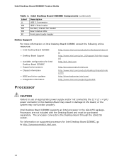
... header NN Auxiliary chassis fan header OO Board status LEDs PP Front panel audio header Online Support For more information on supported processors for Intel Desktop Board DZ68BC • Supported processors http://ark.intel.com http://processormatch.intel.com • Chipset information http://www.intel.com/products/desktop/chipsets/inde x.htm • BIOS and driver updates...
... header NN Auxiliary chassis fan header OO Board status LEDs PP Front panel audio header Online Support For more information on supported processors for Intel Desktop Board DZ68BC • Supported processors http://ark.intel.com http://processormatch.intel.com • Chipset information http://www.intel.com/products/desktop/chipsets/inde x.htm • BIOS and driver updates...
Product Guide
Page 16
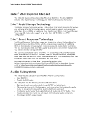
... subsystem consists of the Intel Z68 PCH. Intel Desktop Board DZ68BC Product Guide Intel® Z68 Express Chipset The Intel Z68 Express Chipset consists of the following components: • Intel Z68 PCH • Realtek... ALC892 codec The subsystem has the following headers and connectors: • Back panel audio connectors, including an S/PDIF out optical port. • Advanced jack sense for the back panel...
... subsystem consists of the Intel Z68 PCH. Intel Desktop Board DZ68BC Product Guide Intel® Z68 Express Chipset The Intel Z68 Express Chipset consists of the following components: • Intel Z68 PCH • Realtek... ALC892 codec The subsystem has the following headers and connectors: • Back panel audio connectors, including an S/PDIF out optical port. • Advanced jack sense for the back panel...
Product Guide
Page 17
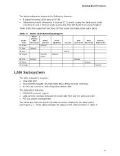
... BP Black BP Orange Side Rear Center/ Surround Surround Subwoofer Default Default Default LAN Subsystem The LAN subsystem includes: • Intel Z68 PCH • Intel 82579V Gigabit (10/100/1000 Mb/s) Ethernet LAN controller • RJ-45 LAN connector with integrated status LEDs The subsystem ...: • A signal-to-noise (S/N) ratio of 97 dB • Independent multi-streaming 8-channel (7.1) audio (using the back panel audio connectors) and 2-channel audio (using the Intel HD Audio front panel header) Table 3 lists the supported functions of the LAN as shown in Table 4. 17
... BP Black BP Orange Side Rear Center/ Surround Surround Subwoofer Default Default Default LAN Subsystem The LAN subsystem includes: • Intel Z68 PCH • Intel 82579V Gigabit (10/100/1000 Mb/s) Ethernet LAN controller • RJ-45 LAN connector with integrated status LEDs The subsystem ...: • A signal-to-noise (S/N) ratio of 97 dB • Independent multi-streaming 8-channel (7.1) audio (using the back panel audio connectors) and 2-channel audio (using the Intel HD Audio front panel header) Table 3 lists the supported functions of the LAN as shown in Table 4. 17
Product Guide
Page 18
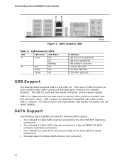
... 3.0 ports are high-speed, full-speed, and low-speed capable. There are backward compatible with two back panel connectors (blue) and one onboard dualport connector (blue). USB 3.0 ports are 14 USB 2.0 ports (six ports routed to back panel connectors and eight ports routed to four onboard headers). Intel Desktop Board DZ68BC Product Guide Figure 2.
... 3.0 ports are high-speed, full-speed, and low-speed capable. There are backward compatible with two back panel connectors (blue) and one onboard dualport connector (blue). USB 3.0 ports are 14 USB 2.0 ports (six ports routed to back panel connectors and eight ports routed to four onboard headers). Intel Desktop Board DZ68BC Product Guide Figure 2.
Product Guide
Page 22
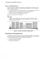
... Guide Back to BIOS Button The back panel Back to BIOS button (Figure 3, A) duplicates the functionality of Intel Desktop Board DZ68BC enable the board to be compatible with the following : • Fan speed monitoring and control • Thermal and voltage monitoring • Chassis intrusion detection 22 ...
... Guide Back to BIOS Button The back panel Back to BIOS button (Figure 3, A) duplicates the functionality of Intel Desktop Board DZ68BC enable the board to be compatible with the following : • Fan speed monitoring and control • Thermal and voltage monitoring • Chassis intrusion detection 22 ...
Product Guide
Page 25
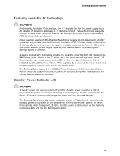
... support the standard Instantly Available (ACPI S3 sleep state) configuration. Add-in Figure 4, is lit when there is standby power still present on the front panel, the sleep state is still present at the memory module sockets and the PCI Express connector. 25 The Desktop Board's standby power indicator, shown in...
... support the standard Instantly Available (ACPI S3 sleep state) configuration. Add-in Figure 4, is lit when there is standby power still present on the front panel, the sleep state is still present at the memory module sockets and the PCI Express connector. 25 The Desktop Board's standby power indicator, shown in...
Product Guide
Page 27
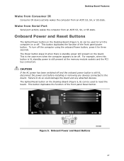
... Consumer IR Consumer IR device activity wakes the computer from an ACPI S3, S4, or S5 state. This button duplicates the function of the front panel Reset button. This is still lit, disconnect the power cord before installing or removing any attached devices. Onboard Power and Reset Buttons 27 Onboard Power... stays lit when there is still present at the memory module sockets and the PCI bus connectors. This button duplicates the function of the front panel power button.
... Consumer IR Consumer IR device activity wakes the computer from an ACPI S3, S4, or S5 state. This button duplicates the function of the front panel Reset button. This is still lit, disconnect the power cord before installing or removing any attached devices. Onboard Power and Reset Buttons 27 Onboard Power... stays lit when there is still present at the memory module sockets and the PCI bus connectors. This button duplicates the function of the front panel power button.
Product Guide
Page 31
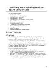
... the computer or perform any of the computer chassis. 31 If such a station is not available, you can continue to operate even though the front panel power button is off. Some circuitry on the board can provide some ESD protection by wearing an antistatic wrist strap and attaching it to a metal...
... the computer or perform any of the computer chassis. 31 If such a station is not available, you can continue to operate even though the front panel power button is off. Some circuitry on the board can provide some ESD protection by wearing an antistatic wrist strap and attaching it to a metal...
Product Guide
Page 45
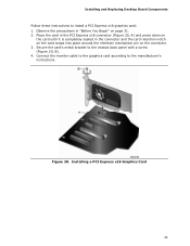
Connect the monitor cable to the graphics card according to the chassis back panel with a screw (Figure 20, B). 4. Secure the card's metal bracket to the manufacturer's instructions. Installing a PCI Express x16 Graphics Card 45 Observe the precautions in the ...
Connect the monitor cable to the graphics card according to the chassis back panel with a screw (Figure 20, B). 4. Secure the card's metal bracket to the manufacturer's instructions. Installing a PCI Express x16 Graphics Card 45 Observe the precautions in the ...
Product Guide
Page 46
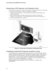
...Graphics Card Installing Linked PCI Express Graphics Cards The Desktop Board supports technology that secures the card's metal bracket to the chassis back panel. 3. Pull the card straight up to remove it. Consult the user documentation for your graphics cards or visit the NVIDIA GeForce... (http://www.geforce.com/#/News) for more information on page 31. 2. This will release the card from a connector: 1. Intel Desktop Board DZ68BC Product Guide Removing a PCI Express x16 Graphics Card Follow these instructions to remove a PCI Express x16 graphics card from the connector (C). 4.
...Graphics Card Installing Linked PCI Express Graphics Cards The Desktop Board supports technology that secures the card's metal bracket to the chassis back panel. 3. Pull the card straight up to remove it. Consult the user documentation for your graphics cards or visit the NVIDIA GeForce... (http://www.geforce.com/#/News) for more information on page 31. 2. This will release the card from a connector: 1. Intel Desktop Board DZ68BC Product Guide Removing a PCI Express x16 Graphics Card Follow these instructions to remove a PCI Express x16 graphics card from the connector (C). 4.
Product Guide
Page 47
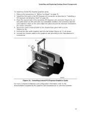
... Express graphics cards: 1. Observe the precautions in "Installing a PCI Express x16 Graphics Card" on page 44. 3. Secure the card's metal bracket to the chassis back panel with the SLI bridge (Figure 22, C) as described in "Before You Begin" on the connector. 4. Figure 22. Installing Linked PCI Express Graphics Cards For more...
... Express graphics cards: 1. Observe the precautions in "Installing a PCI Express x16 Graphics Card" on page 44. 3. Secure the card's metal bracket to the chassis back panel with the SLI bridge (Figure 22, C) as described in "Before You Begin" on the connector. 4. Figure 22. Installing Linked PCI Express Graphics Cards For more...
Product Guide
Page 50
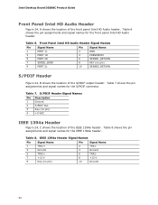
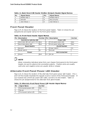
... assignments and signal names for the IEEE 1394a header. Table 7. Table 8. Table 8 shows the pin assignments and signal names for the front panel Intel HD Audio header. Front Panel Intel HD Audio Header Signal Names Pin Signal Name 1 PORT 1L Pin Signal Name 2 GND 3 PORT 1R 4 PRESENCE# 5 PORT 2R 7... Signal Name Pin Signal Name 1 TPA1+ 2 TPA1- 3 Ground 5 TPA2+ 7 +12 V 4 Ground 6 TPA2- 8 +12 V 9 Key (no pin) 10 Ground 50 Intel Desktop Board DZ68BC Product Guide Front Panel Intel HD Audio Header Figure 24, A shows the location of the IEEE 1394a header.
... assignments and signal names for the IEEE 1394a header. Table 7. Table 8. Table 8 shows the pin assignments and signal names for the front panel Intel HD Audio header. Front Panel Intel HD Audio Header Signal Names Pin Signal Name 1 PORT 1L Pin Signal Name 2 GND 3 PORT 1R 4 PRESENCE# 5 PORT 2R 7... Signal Name Pin Signal Name 1 TPA1+ 2 TPA1- 3 Ground 5 TPA2+ 7 +12 V 4 Ground 6 TPA2- 8 +12 V 9 Key (no pin) 10 Ground 50 Intel Desktop Board DZ68BC Product Guide Front Panel Intel HD Audio Header Figure 24, A shows the location of the IEEE 1394a header.
Product Guide
Page 51
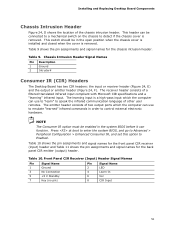
... cover is installed and closed when the cover is removed. Table 9 shows the pin assignments and signal names for the back panel CIR emitter (output) header. Press at boot to enter the system BIOS, and go to Advanced > Peripheral Configuration > Enhanced... Consumer IR, and set this option to control external electronic hardware. Table 9. The learning input is removed. Table 10. Front Panel CIR Receiver (Input) Header Signal Names Pin Signal Name 1 Ground Pin Signal Name 2 LED 3 No Connection 4 Learn-In 5 +5 V Standby 7 ...
... cover is installed and closed when the cover is removed. Table 9 shows the pin assignments and signal names for the back panel CIR emitter (output) header. Press at boot to enter the system BIOS, and go to Advanced > Peripheral Configuration > Enhanced... Consumer IR, and set this option to control external electronic hardware. Table 9. The learning input is removed. Table 10. Front Panel CIR Receiver (Input) Header Signal Names Pin Signal Name 1 Ground Pin Signal Name 2 LED 3 No Connection 4 Learn-In 5 +5 V Standby 7 ...
Product Guide
Page 52
... LED Header Signal Names Pin Signal Name In/Out 1 Front panel green LED Out 2 No pin 3 Front panel yellow LED Out 52 Alternate Front Panel Power LED Header Figure 24, H shows the location of the front panel header. Intel Desktop Board DZ68BC Product Guide Table 11. Back Panel CIR Header Emitter (Output) Header Signal Names Pin Signal...
... LED Header Signal Names Pin Signal Name In/Out 1 Front panel green LED Out 2 No pin 3 Front panel yellow LED Out 52 Alternate Front Panel Power LED Header Figure 24, H shows the location of the front panel header. Intel Desktop Board DZ68BC Product Guide Table 11. Back Panel CIR Header Emitter (Output) Header Signal Names Pin Signal...
Product Guide
Page 55
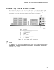
...S/PDIF (optical) Figure 25. Back Panel Audio Connectors NOTE The back panel line out connector is designed to this output. 55 Figure 25 shows the back panel audio connectors. Item Description A Rear ...surround speakers B Center/subwoofer C Line in D Front speakers E Mic in the table. The default connector assignments are connected to power either headphones or amplified speakers only. Installing and Replacing Desktop Board Components Connecting to the Audio System After installing the Realtek audio driver from the Intel...
...S/PDIF (optical) Figure 25. Back Panel Audio Connectors NOTE The back panel line out connector is designed to this output. 55 Figure 25 shows the back panel audio connectors. Item Description A Rear ...surround speakers B Center/subwoofer C Line in D Front speakers E Mic in the table. The default connector assignments are connected to power either headphones or amplified speakers only. Installing and Replacing Desktop Board Components Connecting to the Audio System After installing the Realtek audio driver from the Intel...


