
Product Specification
Page 7
... 1.1.3 Block Diagram 15 1.2 Legacy Considerations 16 1.3 Online Support 16 1.4 Processor 16 1.4.1 PCI Express x16 Graphics 17 1.5 System Memory 17 1.5.1 Memory Configurations 19 1.6 Intel® X79 Express Chipset 21 1.6.1 USB 21 1.6.2 SATA Interfaces 22 1.7 Real-Time Clock Subsystem 23 1.8 Legacy I/O Controller 23 1.8.1 Consumer Infrared (CIR 23 1.9 Audio Subsystem 24 1.9.1 Audio Subsystem Software 24...
... 1.1.3 Block Diagram 15 1.2 Legacy Considerations 16 1.3 Online Support 16 1.4 Processor 16 1.4.1 PCI Express x16 Graphics 17 1.5 System Memory 17 1.5.1 Memory Configurations 19 1.6 Intel® X79 Express Chipset 21 1.6.1 USB 21 1.6.2 SATA Interfaces 22 1.7 Real-Time Clock Subsystem 23 1.8 Legacy I/O Controller 23 1.8.1 Consumer Infrared (CIR 23 1.9 Audio Subsystem 24 1.9.1 Audio Subsystem Software 24...
Product Specification
Page 8
Intel Desktop Board DX79SR Technical Product Specification 1.13 Power Management 32 1.13.1 ACPI 32 1.13.2 Hardware Support 35 1.14 Board Status LEDs 39 1.15 Onboard Power and Reset ... Environmental 65 3 Overview of BIOS Features 3.1 Introduction 67 3.2 BIOS Flash Memory Organization 68 3.3 Resource Configuration 68 3.3.1 PCI Autoconfiguration 68 3.4 System Management BIOS (SMBIOS 69 3.5 Legacy USB Support 69 3.6 BIOS Updates 70 3.6.1 Language Support 70 3.6.2 Custom Splash Screen 71 3.7 BIOS Recovery 71 3.8 Boot Options 72 3.8.1 Optical Drive Boot 72 3.8.2 Network Boot 72...
Intel Desktop Board DX79SR Technical Product Specification 1.13 Power Management 32 1.13.1 ACPI 32 1.13.2 Hardware Support 35 1.14 Board Status LEDs 39 1.15 Onboard Power and Reset ... Environmental 65 3 Overview of BIOS Features 3.1 Introduction 67 3.2 BIOS Flash Memory Organization 68 3.3 Resource Configuration 68 3.3.1 PCI Autoconfiguration 68 3.4 System Management BIOS (SMBIOS 69 3.5 Legacy USB Support 69 3.6 BIOS Updates 70 3.6.1 Language Support 70 3.6.2 Custom Splash Screen 71 3.7 BIOS Recovery 71 3.8 Boot Options 72 3.8.1 Optical Drive Boot 72 3.8.2 Network Boot 72...
Product Specification
Page 9
... ErP Compliance 92 5.1.6 Regulatory Compliance Marks (Board Level 93 5.2 Battery Disposal Information 94 Figures 1. Memory Channel and DIMM Configuration 20 4. Connection Diagram for Front Panel USB 2.0 Headers 57 16. Components Shown in Figure 1 14 3.
... ErP Compliance 92 5.1.6 Regulatory Compliance Marks (Board Level 93 5.2 Battery Disposal Information 94 Figures 1. Memory Channel and DIMM Configuration 20 4. Connection Diagram for Front Panel USB 2.0 Headers 57 16. Components Shown in Figure 1 14 3.
Product Specification
Page 10
...Codes 80 41. Safety Standards 85 43. System Memory Map 45 11. USB 2.0 Headers 51 18. USB 3.0 Connector 52 19. BIOS Setup Configuration Jumper Settings 59 27. Acceptable Drives/Media Types for Intel HD Audio 50 13. Main Power Connector 54 23. Environmental Specifications 65...Audio Header for BIOS Recovery 71 34. Recommended Power Supply Current Values 61 28. Front-panel Power LED Blink Codes 78 38. Intel Desktop Board DX79SR Technical Product Specification 8. Processor, Front and Rear Chassis, and Auxiliary (4-Pin) Fan Headers..... 52 21. States for a Two-...
...Codes 80 41. Safety Standards 85 43. System Memory Map 45 11. USB 2.0 Headers 51 18. USB 3.0 Connector 52 19. BIOS Setup Configuration Jumper Settings 59 27. Acceptable Drives/Media Types for Intel HD Audio 50 13. Main Power Connector 54 23. Environmental Specifications 65...Audio Header for BIOS Recovery 71 34. Recommended Power Supply Current Values 61 28. Front-panel Power LED Blink Codes 78 38. Intel Desktop Board DX79SR Technical Product Specification 8. Processor, Front and Rear Chassis, and Auxiliary (4-Pin) Fan Headers..... 52 21. States for a Two-...
Product Specification
Page 11
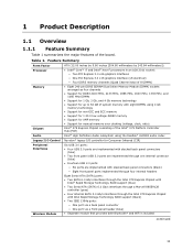
... internal connector (blue) • Fourteen USB 2.0 ports: ― Six ports are implemented with stacked back panel connectors (black) ― Eight front panel ports implemented through four internal headers Wireless Module Eight Serial ATA (SATA) ports: • Two SATA 6.0 Gb/s interfaces through the Intel X79 Express Chipset with Intel® Rapid Storage Technology RAID...
... internal connector (blue) • Fourteen USB 2.0 ports: ― Six ports are implemented with stacked back panel connectors (black) ― Eight front panel ports implemented through four internal headers Wireless Module Eight Serial ATA (SATA) ports: • Two SATA 6.0 Gb/s interfaces through the Intel X79 Express Chipset with Intel® Rapid Storage Technology RAID...
Product Specification
Page 12
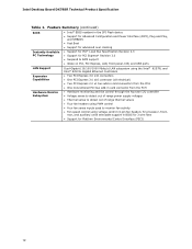
...* Revision 3.0 • Suspend to RAM support • Wake on PCI, PCI Express, LAN, front panel, CIR, and USB ports LAN Support Dual-Gigabit (10/100/1000 Mbits/s) LAN subsystem using the Intel® 82579L and Intel® 82574L Gigabit Ethernet Controllers Expansion Capabilities • Two PCI Express 3.0 x16 connectors • One PCI Express... fan headers for processor, front, rear, and auxiliary) with selectable support in BIOS for 3 wire fans • Support for Platform Environmental Control Interface (PECI) 12 Intel Desktop Board DX79SR Technical Product Specification Table 1.
...* Revision 3.0 • Suspend to RAM support • Wake on PCI, PCI Express, LAN, front panel, CIR, and USB ports LAN Support Dual-Gigabit (10/100/1000 Mbits/s) LAN subsystem using the Intel® 82579L and Intel® 82574L Gigabit Ethernet Controllers Expansion Capabilities • Two PCI Express 3.0 x16 connectors • One PCI Express... fan headers for processor, front, rear, and auxiliary) with selectable support in BIOS for 3 wire fans • Support for Platform Environmental Control Interface (PECI) 12 Intel Desktop Board DX79SR Technical Product Specification Table 1.

Product Specification
Page 14
...connectors through a Marvell 88SE9128 controller (gray) Intel X79 Express Chipset Front panel USB 2.0 headers (4) Consumer IR emitter (output) header BIOS Setup configuration jumper block Power Fault LED Front panel USB 3.0 connector Alternate front panel power LED ...header Consumer IR receiver (input) header Voltage measurement test points Front panel header Post Code LED display Front panel IEEE 1394a header Onboard Reset button Onboard Power button Chassis intrusion header Auxiliary fan header Board Status LEDs 14 Intel Desktop Board DX79SR...
...connectors through a Marvell 88SE9128 controller (gray) Intel X79 Express Chipset Front panel USB 2.0 headers (4) Consumer IR emitter (output) header BIOS Setup configuration jumper block Power Fault LED Front panel USB 3.0 connector Alternate front panel power LED ...header Consumer IR receiver (input) header Voltage measurement test points Front panel header Post Code LED display Front panel IEEE 1394a header Onboard Reset button Onboard Power button Chassis intrusion header Auxiliary fan header Board Status LEDs 14 Intel Desktop Board DX79SR...

Product Specification
Page 21
... used by two NEC* UPD720200 controllers. The Intel X79 Express Chipset provides the USB controller for the board's I/O paths. The port arrangement is as follows: • Four USB 3.0 ports are implemented with stacked back panel connectors (blue) • Two USB 3.0 front panel ports implemented through one internal ...Refer to Figure 11, page 46 Figure 13, page 48 21 The six USB 3.0 ports are provided by the chipset Refer to http://www.intel.com/products/desktop/chipsets/index.htm Chapter 2 1.6.1 USB The board supports up to the cable. NOTE Computer systems that meets the...
... used by two NEC* UPD720200 controllers. The Intel X79 Express Chipset provides the USB controller for the board's I/O paths. The port arrangement is as follows: • Four USB 3.0 ports are implemented with stacked back panel connectors (blue) • Two USB 3.0 front panel ports implemented through one internal ...Refer to Figure 11, page 46 Figure 13, page 48 21 The six USB 3.0 ports are provided by the chipset Refer to http://www.intel.com/products/desktop/chipsets/index.htm Chapter 2 1.6.1 USB The board supports up to the cable. NOTE Computer systems that meets the...

Product Specification
Page 32
...) • Hardware support: ⎯ Power connector ⎯ Fan headers ⎯ LAN wake capabilities ⎯ Instantly Available PC technology ⎯ Wake from USB ⎯ PME# signal wake-up support ⎯ WAKE# signal wake-up (ACPI G0 - working state) Soft-off ) On (ACPI G0 - sleeping... state) Fail safe power-off (ACPI G2/G5 - sleeping state) Sleep (ACPI G1 - working state) Sleep (ACPI G1 - Intel Desktop Board DX79SR Technical Product Specification 1.13 Power Management Power management is in this state... The use of Pressing the Power Switch If the system is ...
...) • Hardware support: ⎯ Power connector ⎯ Fan headers ⎯ LAN wake capabilities ⎯ Instantly Available PC technology ⎯ Wake from USB ⎯ PME# signal wake-up support ⎯ WAKE# signal wake-up (ACPI G0 - working state) Soft-off ) On (ACPI G0 - sleeping... state) Fail safe power-off (ACPI G2/G5 - sleeping state) Sleep (ACPI G1 - working state) Sleep (ACPI G1 - Intel Desktop Board DX79SR Technical Product Specification 1.13 Power Management Power management is in this state... The use of Pressing the Power Switch If the system is ...
Product Specification
Page 34
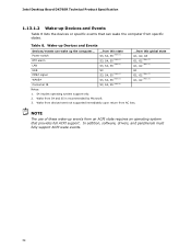
... global state G1, G2, G3 G1, G2 (Note 3) G1, G2 (Note 3) USB PME# signal WAKE# Consumer IR S3 S3, S4, S5 (Note 1) S3, S4, S5 (Note 1) S3, S4, S5 (Note 2) G1 G1, G2 (Note 3) G1, G2 (Note 3) Notes: 1. Intel Desktop Board DX79SR Technical Product Specification 1.13.1.2 Wake-up Devices and Events Table 8 lists...
... global state G1, G2, G3 G1, G2 (Note 3) G1, G2 (Note 3) USB PME# signal WAKE# Consumer IR S3 S3, S4, S5 (Note 1) S3, S4, S5 (Note 1) S3, S4, S5 (Note 2) G1 G1, G2 (Note 3) G1, G2 (Note 3) Notes: 1. Intel Desktop Board DX79SR Technical Product Specification 1.13.1.2 Wake-up Devices and Events Table 8 lists...

Product Specification
Page 35
... the computer returns to the power state it was interrupted (on the wake devices supported and manufacturing options. NOTE The use of Wake from USB from the +5 V standby line. Failure to Figure 13, page 48 Table 22, page 54 35 The computer's response can damage the ...power management hardware features, including: • Power connector • Fan headers • LAN wake capabilities • Instantly Available PC technology • Wake from USB • PME# signal wake-up support • WAKE# signal wake-up support • Wake from Consumer IR • Wake from S5 • Power...
... the computer returns to the power state it was interrupted (on the wake devices supported and manufacturing options. NOTE The use of Wake from USB from the +5 V standby line. Failure to Figure 13, page 48 Table 22, page 54 35 The computer's response can damage the ...power management hardware features, including: • Power connector • Fan headers • LAN wake capabilities • Instantly Available PC technology • Wake from USB • PME# signal wake-up support • WAKE# signal wake-up support • Wake from Consumer IR • Wake from S5 • Power...

Product Specification
Page 37
... to provide adequate standby current when implementing Instantly Available PC technology can damage the power supply. Add-in boards that supports Wake from USB and is supported by a wake-up Support When the WAKE# signal on the PCI Express bus is asserted, the computer wakes from...The board supports the PCI Bus Power Management Interface Specification. NOTE Wake from USB requires the use of a USB peripheral that also support this specification can participate in cards, and drivers. 1.13.2.5 Wake from USB USB bus activity wakes the computer from the S3 state. The use of Instantly ...
... to provide adequate standby current when implementing Instantly Available PC technology can damage the power supply. Add-in boards that supports Wake from USB and is supported by a wake-up Support When the WAKE# signal on the PCI Express bus is asserted, the computer wakes from...The board supports the PCI Bus Power Management Interface Specification. NOTE Wake from USB requires the use of a USB peripheral that also support this specification can participate in cards, and drivers. 1.13.2.5 Wake from USB USB bus activity wakes the computer from the S3 state. The use of Instantly ...
Product Specification
Page 40
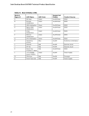
Board Status LEDs Item in Figure 8 LED Name LED Color A OS Start Green B Storage Green Initialization C USB Initialization Green D Option ROM Green Initialization E Video Green Initialization F Memory Green Initialization G CPU Initialization Green H Hard Drive Blue Activity I CPU Hot Red J VR Hot Red K ... On/Off Control Source BIOS BIOS BIOS BIOS BIOS BIOS BIOS Hard drive controller(s) Discrete circuit Discrete circuit BIOS Power Supply Processor Power Supply 40 Intel Desktop Board DX79SR Technical Product Specification Table 9.
Board Status LEDs Item in Figure 8 LED Name LED Color A OS Start Green B Storage Green Initialization C USB Initialization Green D Option ROM Green Initialization E Video Green Initialization F Memory Green Initialization G CPU Initialization Green H Hard Drive Blue Activity I CPU Hot Red J VR Hot Red K ... On/Off Control Source BIOS BIOS BIOS BIOS BIOS BIOS BIOS Hard drive controller(s) Discrete circuit Discrete circuit BIOS Power Supply Processor Power Supply 40 Intel Desktop Board DX79SR Technical Product Specification Table 9.
Product Specification
Page 45
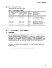
... memory 2.2 Connectors and Headers CAUTION Only the following connectors and headers have overcurrent protection: back panel and front panel USB, as well as fans and internal peripherals. Furthermore, improper connection of USB or 1394 header single wire connectors may eventually overload the overcurrent protection and cause damage to the computer's chassis. The...
... memory 2.2 Connectors and Headers CAUTION Only the following connectors and headers have overcurrent protection: back panel and front panel USB, as well as fans and internal peripherals. Furthermore, improper connection of USB or 1394 header single wire connectors may eventually overload the overcurrent protection and cause damage to the computer's chassis. The...

Product Specification
Page 46
Intel Desktop Board DX79SR Technical Product Specification 2.2.1 Back Panel Connectors Figure 11 shows the location of the back panel connectors for the board. Poor audio quality occurs if passive (non-amplified) speakers are connected to BIOS button USB 3.0 ports USB 3.0 ports LAN connector USB 2.0 ports IEEE 1394a connector USB 2.0 ports LAN connector USB 2.0 ports Rear surround Center channel...
Intel Desktop Board DX79SR Technical Product Specification 2.2.1 Back Panel Connectors Figure 11 shows the location of the back panel connectors for the board. Poor audio quality occurs if passive (non-amplified) speakers are connected to BIOS button USB 3.0 ports USB 3.0 ports LAN connector USB 2.0 ports IEEE 1394a connector USB 2.0 ports LAN connector USB 2.0 ports Rear surround Center channel...

Product Specification
Page 49
... 3.0 Gb/s connectors through the PCH (black) Q SATA 6.0 Gb/s connectors through a Marvell 88SE9128 controller (gray) R Front panel USB 2.0 header S Front panel USB 2.0 header T Front panel USB 2.0 header U Front panel USB 2.0 header V Consumer IR emitter (output) header W Front panel USB 3.0 connector X Consumer IR receiver (input) header Y Alternate front panel power LED header Z Front panel header AA Front...
... 3.0 Gb/s connectors through the PCH (black) Q SATA 6.0 Gb/s connectors through a Marvell 88SE9128 controller (gray) R Front panel USB 2.0 header S Front panel USB 2.0 header T Front panel USB 2.0 header U Front panel USB 2.0 header V Consumer IR emitter (output) header W Front panel USB 3.0 connector X Consumer IR receiver (input) header Y Alternate front panel power LED header Z Front panel header AA Front...

Product Specification
Page 51
USB 2.0 Headers Pin Signal Name 1 +5 V DC 2 D− 3 D+ 4 Ground 5 Key (no pin) Table 15. SATA Connectors Pin Signal Name 1 Ground 2 TXP 3 TXN 4 Ground 5 RXN 6 RXP 7 Ground Table 16. Table 14. IEEE 1394a Header Pin Signal Name 1 Data A (positive) 3 Ground 5 Data B (positive) 7 +12 V DC 9 Key (no pin) Technical Reference Pin 2 4 6 8 10 Signal Name Data A (negative) Ground Data B (negative) +12 V DC Ground 51 S/PDIF Header Pin Signal Name 1 Ground 2 S/PDIF out 3 Key (no pin) 4 +5 VDC Table 17.
USB 2.0 Headers Pin Signal Name 1 +5 V DC 2 D− 3 D+ 4 Ground 5 Key (no pin) Table 15. SATA Connectors Pin Signal Name 1 Ground 2 TXP 3 TXN 4 Ground 5 RXN 6 RXP 7 Ground Table 16. Table 14. IEEE 1394a Header Pin Signal Name 1 Data A (positive) 3 Ground 5 Data B (positive) 7 +12 V DC 9 Key (no pin) Technical Reference Pin 2 4 6 8 10 Signal Name Data A (negative) Ground Data B (negative) +12 V DC Ground 51 S/PDIF Header Pin Signal Name 1 Ground 2 S/PDIF out 3 Key (no pin) 4 +5 VDC Table 17.

Product Specification
Page 52
USB 3.0 Connector Pin Signal Name 1 Vbus 2 IntA_P1_SSRX− 3 IntA_P1_SSRX+ 4 GND 5 IntA_P1_SSTX− 6 IntA_P1_SSTX+ 7 GND 8 IntA_P1_D− 9 IntA_P1_D+ 10 ID 11 IntA_P2_D+ 12 IntA_P2_D− ...; Ground USB3 ICC Port2 SuperSpeed Rx+ USB3 ICC Port2 SuperSpeed Rx+ Power Table 19. Chassis Intrusion Header Pin Signal Name 1 Intruder# 2 Ground Table 20. Intel Desktop Board DX79SR Technical Product Specification Table 18. Processor, Front and Rear Chassis, and Auxiliary (4-Pin) Fan Headers Pin Signal Name 1 Ground (Note) 2 +12 V 3 FAN_TACH 4 ...
USB 3.0 Connector Pin Signal Name 1 Vbus 2 IntA_P1_SSRX− 3 IntA_P1_SSRX+ 4 GND 5 IntA_P1_SSTX− 6 IntA_P1_SSTX+ 7 GND 8 IntA_P1_D− 9 IntA_P1_D+ 10 ID 11 IntA_P2_D+ 12 IntA_P2_D− ...; Ground USB3 ICC Port2 SuperSpeed Rx+ USB3 ICC Port2 SuperSpeed Rx+ Power Table 19. Chassis Intrusion Header Pin Signal Name 1 Intruder# 2 Ground Table 20. Intel Desktop Board DX79SR Technical Product Specification Table 18. Processor, Front and Rear Chassis, and Auxiliary (4-Pin) Fan Headers Pin Signal Name 1 Ground (Note) 2 +12 V 3 FAN_TACH 4 ...

Product Specification
Page 57
Connection Diagram for the front panel USB 2.0 headers. Technical Reference 2.2.2.5 Front Panel USB 2.0 Headers Figure 15 is fused. • Use only a front panel USB 2.0 connector that conforms to the USB 2.0 specification for high-speed USB devices. NOTE • The +5 V DC power on the headers is a connection diagram for Front Panel USB 2.0 Headers 57 Figure 15.
Connection Diagram for the front panel USB 2.0 headers. Technical Reference 2.2.2.5 Front Panel USB 2.0 Headers Figure 15 is fused. • Use only a front panel USB 2.0 connector that conforms to the USB 2.0 specification for high-speed USB devices. NOTE • The +5 V DC power on the headers is a connection diagram for Front Panel USB 2.0 Headers 57 Figure 15.
Product Specification
Page 69
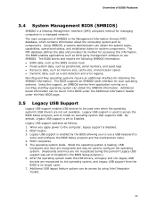
... power to Enabled. While the operating system is loading, USB keyboards and mice are recognized and may be used even when the operating system's USB drivers are recognized by using Intel Integrator Toolkit. 69 Additional USB legacy feature options can be found in the BIOS under ...the Additional Information header under the Main BIOS page. 3.5 Legacy USB Support Legacy USB support enables USB devices to use SMBIOS. ...
... power to Enabled. While the operating system is loading, USB keyboards and mice are recognized and may be used even when the operating system's USB drivers are recognized by using Intel Integrator Toolkit. 69 Additional USB legacy feature options can be found in the BIOS under ...the Additional Information header under the Main BIOS page. 3.5 Legacy USB Support Legacy USB support enables USB devices to use SMBIOS. ...

