

Intel Desktop Board DX58SO2 Technical Product Specification
Page 8
...Serial ATA Connectors 45 13. Auxiliary Front Panel Power/Sleep LED Header 47 18. Main Power Connector 49 20. Auxiliary PCI Express Graphics Power Connector 49 21. BIOS Setup Program Menu Bar 62 30. Typical Port 80h POST Sequence 77 40. Component-side Connectors ...AcceptableDrives/Media Types for Components 59 28. Front Panel Header 50 22. Environmental Specifications 60 29. BIOS Error Messages 72 37. Intel Desktop Board DX58SO2 Technical Product Specification Tables 1. Audio Jack Support 22 5. Front Panel Audio Header 45 12. Front Panel IEEE 1394a Header 45 14...
...Serial ATA Connectors 45 13. Auxiliary Front Panel Power/Sleep LED Header 47 18. Main Power Connector 49 20. Auxiliary PCI Express Graphics Power Connector 49 21. BIOS Setup Program Menu Bar 62 30. Typical Port 80h POST Sequence 77 40. Component-side Connectors ...AcceptableDrives/Media Types for Components 59 28. Front Panel Header 50 22. Environmental Specifications 60 29. BIOS Error Messages 72 37. Intel Desktop Board DX58SO2 Technical Product Specification Tables 1. Audio Jack Support 22 5. Front Panel Audio Header 45 12. Front Panel IEEE 1394a Header 45 14...

Intel Desktop Board DX58SO2 Technical Product Specification
Page 18
... USB controller for the board's I /O Controller Hub (ICH10R) The IOH component provides interfaces to the processor and the PCI Express graphics connectors. Intel Desktop Board DX58SO2 Technical Product Specification 1.6 Intel® X58 Chipset The Intel X58 chipset consists of the front panel USB headers Refer to Figure 10, page 42 Figure 11, page 43 18
... USB controller for the board's I /O Controller Hub (ICH10R) The IOH component provides interfaces to the processor and the PCI Express graphics connectors. Intel Desktop Board DX58SO2 Technical Product Specification 1.6 Intel® X58 Chipset The Intel X58 chipset consists of the front panel USB headers Refer to Figure 10, page 42 Figure 11, page 43 18

Intel Desktop Board DX58SO2 Technical Product Specification
Page 49
... Name 1 +3.3 V 2 +3.3 V 3 Ground Pin Signal Name 13 +3.3 V 14 -12 V 15 Ground 4 +5 V 5 Ground 6 +5 V 7 Ground 16 PS-ON# (power supply remote on page 56 49 Auxiliary PCI Express Graphics Power Connector Pin Signal Name 1 +12 V 2 1 x 4 connector detect 3 Ground 4 +5 V For information about Power supply considerations Refer to Section 2.5.1 on /off) 17 Ground 18 Ground 19...
... Name 1 +3.3 V 2 +3.3 V 3 Ground Pin Signal Name 13 +3.3 V 14 -12 V 15 Ground 4 +5 V 5 Ground 6 +5 V 7 Ground 16 PS-ON# (power supply remote on page 56 49 Auxiliary PCI Express Graphics Power Connector Pin Signal Name 1 +12 V 2 1 x 4 connector detect 3 Ground 4 +5 V For information about Power supply considerations Refer to Section 2.5.1 on /off) 17 Ground 18 Ground 19...

English Product Guide
Page 6
Intel Desktop Board DX58SO2 Product Guide 2 Installing and Replacing Desktop Board Components Before You Begin 31 Installation Precautions 32...and Removing PCI Express x16 Add-in Cards 43 Installing PCI Express x16 Graphics Cards 43 Removing a PCI Express x16 Add-in Card 44 Installing Linked PCI Express x16 Graphics Cards 45 Connecting the Serial ATA (SATA) Cables 47 Connecting to .../Bluetooth* Module in a Desktop Chassis 63 3 Updating the BIOS Updating the BIOS with the Intel® Express BIOS Update Utility 65 Updating the BIOS Using the F7 Function Key 66 Updating the BIOS with the...
Intel Desktop Board DX58SO2 Product Guide 2 Installing and Replacing Desktop Board Components Before You Begin 31 Installation Precautions 32...and Removing PCI Express x16 Add-in Cards 43 Installing PCI Express x16 Graphics Cards 43 Removing a PCI Express x16 Add-in Card 44 Installing Linked PCI Express x16 Graphics Cards 45 Connecting the Serial ATA (SATA) Cables 47 Connecting to .../Bluetooth* Module in a Desktop Chassis 63 3 Updating the BIOS Updating the BIOS with the Intel® Express BIOS Update Utility 65 Updating the BIOS Using the F7 Function Key 66 Updating the BIOS with the...

English Product Guide
Page 8
Location of the BIOS Configuration Jumper Block 56 28. Removing the Battery 62 29. Feature Summary 9 2. Intel Desktop Board DX58SO2 Components 13 3. S/PDIF Header Signal Names 49 7. Front Panel CIR Receiver (Input) Header Signal Names 50 9. BIOS Error ...18. Regulatory Compliance Marks 88 viii Installing Linked PCI Express Graphics Cards 46 22. Internal Headers 48 24. LAN Connector LEDs 18 4. Front Panel Header Signal Names 52 14. Installing a DIMM 42 19. Intel Desktop Board DX58SO2 China RoHS Material Self Declaration Table............84 Tables 1. Jumper ...
Location of the BIOS Configuration Jumper Block 56 28. Removing the Battery 62 29. Feature Summary 9 2. Intel Desktop Board DX58SO2 Components 13 3. S/PDIF Header Signal Names 49 7. Front Panel CIR Receiver (Input) Header Signal Names 50 9. BIOS Error ...18. Regulatory Compliance Marks 88 viii Installing Linked PCI Express Graphics Cards 46 22. Internal Headers 48 24. LAN Connector LEDs 18 4. Front Panel Header Signal Names 52 14. Installing a DIMM 42 19. Intel Desktop Board DX58SO2 China RoHS Material Self Declaration Table............84 Tables 1. Jumper ...

English Product Guide
Page 9
... Features This chapter briefly describes the features of : • Intel X58 Express Chipset I/O Hub (IOH) • Intel® I/O Controller Hub (ICH10R) supporting Intel® Matrix Storage Technology Graphics Audio Expansion Capabilities Support for multiple PCI Express* graphics cards including linked cards using Nvidia* SLI* technology and ATI ...One port routed to the back panel ― One port routed to 24 GB of system memory Intel® X58 Express Chipset consisting of Intel® Desktop Board DX58SO2. Table 1. Table 1 summarizes the major features of the Desktop Board.
... Features This chapter briefly describes the features of : • Intel X58 Express Chipset I/O Hub (IOH) • Intel® I/O Controller Hub (ICH10R) supporting Intel® Matrix Storage Technology Graphics Audio Expansion Capabilities Support for multiple PCI Express* graphics cards including linked cards using Nvidia* SLI* technology and ATI ...One port routed to the back panel ― One port routed to 24 GB of system memory Intel® X58 Express Chipset consisting of Intel® Desktop Board DX58SO2. Table 1. Table 1 summarizes the major features of the Desktop Board.

English Product Guide
Page 15
...systems are limited to this effect on this desktop board requires compatible XMP-enabled memory or advanced knowledge of the memory used by add-in graphics cards. The BIOS will see a notification to a maximum of 4 GB of memory. The Desktop Board supports the following links or ... of BIOS and manual memory tuning. Individual results may vary. • Support for more information about: • SDRAM specifications, http://www.intel.com/technology/memory/ • Installing memory, page 40 in Chapter 2 15 Desktop Board Features Main Memory NOTE To be fully compliant with all...
...systems are limited to this effect on this desktop board requires compatible XMP-enabled memory or advanced knowledge of the memory used by add-in graphics cards. The BIOS will see a notification to a maximum of 4 GB of memory. The Desktop Board supports the following links or ... of BIOS and manual memory tuning. Individual results may vary. • Support for more information about: • SDRAM specifications, http://www.intel.com/technology/memory/ • Installing memory, page 40 in Chapter 2 15 Desktop Board Features Main Memory NOTE To be fully compliant with all...

English Product Guide
Page 43
...be damaged. Depending on page 31. 2. Observe the precautions in the PCI Express connector before you are installing a single PCI Express x16 graphics card, install it is fully seated in "Before You Begin" on the over-current protection of the power supply, certain Desktop Board .... Replace the computer's cover and reconnect the AC power cord. Turn off all peripheral devices connected to the computer. Installing PCI Express x16 Graphics Cards If you power on page 31. 2. Observe the precautions in the PCI Express primary connector (Figure 19, A) for optimum performance. ...
...be damaged. Depending on page 31. 2. Observe the precautions in the PCI Express connector before you are installing a single PCI Express x16 graphics card, install it is fully seated in "Before You Begin" on the over-current protection of the power supply, certain Desktop Board .... Replace the computer's cover and reconnect the AC power cord. Turn off all peripheral devices connected to the computer. Installing PCI Express x16 Graphics Cards If you power on page 31. 2. Observe the precautions in the PCI Express primary connector (Figure 19, A) for optimum performance. ...

English Product Guide
Page 45
Installing and Replacing Desktop Board Components Figure 20. To install two linked PCI Express graphics cards: 1. When installing linked graphics cards in "Installing PCI Express x16 Graphics Cards" on page 31. 2. Install the first card in the PCI Express x16 connector as described in the...Removing a PCI Express x16 Card Installing Linked PCI Express x16 Graphics Cards The Desktop Board supports the use of linked PCI Express x16 graphics cards with the Desktop Board to the documentation supplied by the graphics card manufacturer or visit their website. Use the connectors included with...
Installing and Replacing Desktop Board Components Figure 20. To install two linked PCI Express graphics cards: 1. When installing linked graphics cards in "Installing PCI Express x16 Graphics Cards" on page 31. 2. Install the first card in the PCI Express x16 connector as described in the...Removing a PCI Express x16 Card Installing Linked PCI Express x16 Graphics Cards The Desktop Board supports the use of linked PCI Express x16 graphics cards with the Desktop Board to the documentation supplied by the graphics card manufacturer or visit their website. Use the connectors included with...
English Product Guide
Page 46
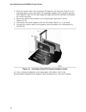
.... 4. Connect the monitor cable to the graphics card according to the documentation supplied by the graphics card manufacturer or visit their website. 46 Figure 21. Installing Linked PCI Express Graphics Cards For more complete installation and configuration information... refer to the manufacturer's instructions. Connect the two cards together with a screw (Figure 21, B). 5. Secure the card's metal bracket to the chassis back panel with the SLI bridge (Figure 21, C) as shown. 6. Intel Desktop Board DX58SO2...
.... 4. Connect the monitor cable to the graphics card according to the documentation supplied by the graphics card manufacturer or visit their website. 46 Figure 21. Installing Linked PCI Express Graphics Cards For more complete installation and configuration information... refer to the manufacturer's instructions. Connect the two cards together with a screw (Figure 21, B). 5. Secure the card's metal bracket to the chassis back panel with the SLI bridge (Figure 21, C) as shown. 6. Intel Desktop Board DX58SO2...


