Product Guide
Page 5
...Desktop Board Features Supported Operating Systems 10 Desktop Board Components 11 Processor ...13 Main Memory ...13 Intel® Q965 Express Chipset 15 Intel Q965 Graphics Subsystem 15 GMA 3000 Graphics Controller 15 Onboard Audio Subsystem 16 Input/Output (I/O) Controller 16 LAN Subsystem 17 LAN Subsystem Software 17 RJ-45 LAN Connector LEDs 17 Intel® Active Management Technology (Intel...Speaker ...25 Battery ...25 Real-Time Clock 25 2 Installing and Replacing Desktop Board Components Before You Begin 27 Installation Precautions 28 Prevent Power Supply Overload 28 Observe Safety ...
...Desktop Board Features Supported Operating Systems 10 Desktop Board Components 11 Processor ...13 Main Memory ...13 Intel® Q965 Express Chipset 15 Intel Q965 Graphics Subsystem 15 GMA 3000 Graphics Controller 15 Onboard Audio Subsystem 16 Input/Output (I/O) Controller 16 LAN Subsystem 17 LAN Subsystem Software 17 RJ-45 LAN Connector LEDs 17 Intel® Active Management Technology (Intel...Speaker ...25 Battery ...25 Real-Time Clock 25 2 Installing and Replacing Desktop Board Components Before You Begin 27 Installation Precautions 28 Prevent Power Supply Overload 28 Observe Safety ...
Product Guide
Page 6
Intel Desktop Board DQ965GF Product Guide Installing and Removing the Desktop Board 30 Installing and Removing a Processor 31 Installing a Processor 31 Installing the Processor Fan Heat Sink 34 Connecting the Processor Fan Heat Sink Cable 34 Removing the Processor 35 Installing and Removing Memory 35 Guidelines for Dual Channel Memory ...42 Connecting the Serial ATA (SATA) Cable 43 Connecting to Internal Headers 44 Installing a Front Panel Audio Solution for Intel® High Definition Audio 45 Connecting to the USB 2.0 Headers 46 Connecting to the Front Panel Header 46 Connecting to...
Intel Desktop Board DQ965GF Product Guide Installing and Removing the Desktop Board 30 Installing and Removing a Processor 31 Installing a Processor 31 Installing the Processor Fan Heat Sink 34 Connecting the Processor Fan Heat Sink Cable 34 Removing the Processor 35 Installing and Removing Memory 35 Guidelines for Dual Channel Memory ...42 Connecting the Serial ATA (SATA) Cable 43 Connecting to Internal Headers 44 Installing a Front Panel Audio Solution for Intel® High Definition Audio 45 Connecting to the USB 2.0 Headers 46 Connecting to the Front Panel Header 46 Connecting to...
Product Guide
Page 7
...31 8. Install the Processor 33 11. Dual Channel Memory Configuration Example 3 37 16. Connecting Power Supply Cables 50 26. Location of the BIOS Configuration Jumper Block 52 28. Removing the Battery 59 30. SATA Port Mapping for Desktop Board DQ965GF 65 31. Desktop Board DQ965GF Mounting Screw Hole ... Installing a PCI Express x16 Card 40 19. Location of Other Connectors and Headers 51 27. Original SATA Port Mapping for Desktop Board DQ965GF After RAID is Enabled 66 vii Close the Load Plate 33 12. Removing a PCI Express x16 Card 41 20. Internal Headers...
...31 8. Install the Processor 33 11. Dual Channel Memory Configuration Example 3 37 16. Connecting Power Supply Cables 50 26. Location of the BIOS Configuration Jumper Block 52 28. Removing the Battery 59 30. SATA Port Mapping for Desktop Board DQ965GF 65 31. Desktop Board DQ965GF Mounting Screw Hole ... Installing a PCI Express x16 Card 40 19. Location of Other Connectors and Headers 51 27. Original SATA Port Mapping for Desktop Board DQ965GF After RAID is Enabled 66 vii Close the Load Plate 33 12. Removing a PCI Express x16 Card 41 20. Internal Headers...
Product Guide
Page 9
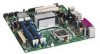
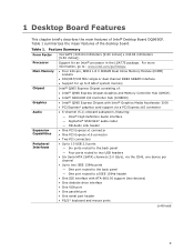
... the major features of Intel® Desktop Board DQ965GF. 1 Desktop Board Features This chapter briefly describes the main features of the desktop board. Feature Summary Form Factor Processor Main Memory Chipset Graphics Audio Expansion Capabilities Peripheral Interfaces microATX (243.84 millimeters [9.60 inches] x 243.84 millimeters [9.60 inches]) Support for up to 8 GB of system memory Intel® Q965 Express...
... the major features of Intel® Desktop Board DQ965GF. 1 Desktop Board Features This chapter briefly describes the main features of the desktop board. Feature Summary Form Factor Processor Main Memory Chipset Graphics Audio Expansion Capabilities Peripheral Interfaces microATX (243.84 millimeters [9.60 inches] x 243.84 millimeters [9.60 inches]) Support for up to 8 GB of system memory Intel® Q965 Express...
Product Guide
Page 12
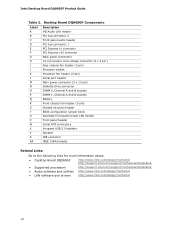
... 1394a header Related Links: Go to the following links for more information about: • Desktop Board DQ965GF • Supported processors • Audio software and utilities • LAN software and drivers http://www.intel.com/design/motherbd http://support.intel.com/support/motherboards/desktop http://support.intel.com/support/motherboards/desktop http://www.intel.com/design/motherbd http://www.intel.com/design/motherbd 12
... 1394a header Related Links: Go to the following links for more information about: • Desktop Board DQ965GF • Supported processors • Audio software and utilities • LAN software and drivers http://www.intel.com/design/motherbd http://support.intel.com/support/motherboards/desktop http://support.intel.com/support/motherboards/desktop http://www.intel.com/design/motherbd http://www.intel.com/design/motherbd 12
Product Guide
Page 13
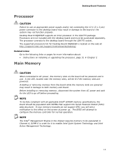
...intel.com/support/motherboards/desktop/ Related Links: Go to the following links or pages for the LED to the desktop board through the LGA775 socket. Installing or removing memory from AC power and wait for more information about: • Instructions on installing or upgrading the processor... When connected to AC power, the memory slots on the web at power up. Desktop Board Features Processor CAUTION Failure to use . The BIOS will be purchased separately. Desktop Board DQ965GF supports an Intel processor in use an appropriate power supply and/or not connecting the 12 V (2 x ...
...intel.com/support/motherboards/desktop/ Related Links: Go to the following links or pages for the LED to the desktop board through the LGA775 socket. Installing or removing memory from AC power and wait for more information about: • Instructions on installing or upgrading the processor... When connected to AC power, the memory slots on the web at power up. Desktop Board Features Processor CAUTION Failure to use . The BIOS will be purchased separately. Desktop Board DQ965GF supports an Intel processor in use an appropriate power supply and/or not connecting the 12 V (2 x ...
Product Guide
Page 19
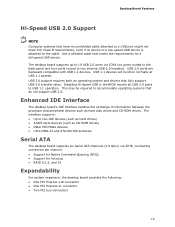
...or a low-speed USB device is attached to the cable. The desktop board supports up to two internal USB 2.0 headers). Enhanced IDE Interface The desktop board's IDE interface handles the exchange of information between the processor and peripheral devices such as CD-ROM drives) • Older PIO... Mode devices • Ultra DMA-33 and ATA-66/100 protocols Serial ATA The desktop board supports six Serial ATA ...
...or a low-speed USB device is attached to the cable. The desktop board supports up to two internal USB 2.0 headers). Enhanced IDE Interface The desktop board's IDE interface handles the exchange of information between the processor and peripheral devices such as CD-ROM drives) • Older PIO... Mode devices • Ultra DMA-33 and ATA-66/100 protocols Serial ATA The desktop board supports six Serial ATA ...

Product Guide
Page 21
...intel.com/design/motherbd http://support.intel.com/support/motherboards/desktop/ Hardware Management Features The hardware management features of the chassis intrusion header. 21 The security feature uses a mechanical switch on the chassis that can adjust fan speed or switch the fans off as needed Chassis Intrusion Detection The board...for the location of Desktop Board DQ965GF enable the board to be installed in the Channel A, DIMM 0 socket to enable Intel® Quiet System ...operations when the keys are being used unencrypted in the processor, GMCH, and ICH8 plus an onboard remote sensor &#...
...intel.com/design/motherbd http://support.intel.com/support/motherboards/desktop/ Hardware Management Features The hardware management features of the chassis intrusion header. 21 The security feature uses a mechanical switch on the chassis that can adjust fan speed or switch the fans off as needed Chassis Intrusion Detection The board...for the location of Desktop Board DQ965GF enable the board to be installed in the Channel A, DIMM 0 socket to enable Intel® Quiet System ...operations when the keys are being used unencrypted in the processor, GMCH, and ICH8 plus an onboard remote sensor &#...

Product Guide
Page 22
Intel Desktop Board DQ965GF Product Guide Power Management Features Power management is implemented at several levels, including: &#... it was in before power was interrupted (either on page 50 for the location of ACPI with the desktop board requires an operating system that provides full ACPI support. The computer's response can turn off the computer power...Power State feature in the ACPI S0 state. • The fans are off ). The desktop board has two power connectors. The desktop board has a 4-pin processor fan header and two 3-pin chassis fan headers. 22 See Figure 25 on or off ...
Intel Desktop Board DQ965GF Product Guide Power Management Features Power management is implemented at several levels, including: &#... it was in before power was interrupted (either on page 50 for the location of ACPI with the desktop board requires an operating system that provides full ACPI support. The computer's response can turn off the computer power...Power State feature in the ACPI S0 state. • The fans are off ). The desktop board has two power connectors. The desktop board has a 4-pin processor fan header and two 3-pin chassis fan headers. 22 See Figure 25 on or off ...
Product Guide
Page 27
... an antistatic wrist strap and attaching it to operate even though the front panel power button is off. Some circuitry on the board can damage components. If such a station is not available, you can result in personal injury or equipment damage. Perform the ... using an antistatic wrist strap and a conductive foam pad. 2 Installing and Replacing Desktop Board Components This chapter tells you how to: • Install the I/O shield • Install and remove the desktop board • Install and remove a processor • Install and remove memory • Install and remove a PCI Express x16...
... an antistatic wrist strap and attaching it to operate even though the front panel power button is off. Some circuitry on the board can damage components. If such a station is not available, you can result in personal injury or equipment damage. Perform the ... using an antistatic wrist strap and a conductive foam pad. 2 Installing and Replacing Desktop Board Components This chapter tells you how to: • Install the I/O shield • Install and remove the desktop board • Install and remove a processor • Install and remove memory • Install and remove a PCI Express x16...

Product Guide
Page 28
...on page 71. 28 Related Links For information about regulatory compliance, go to qualified technical personnel. Intel Desktop Board DQ965GF Product Guide Installation Precautions When you install and test the Intel desktop board, observe all the modules within the computer is less than the output current rating of each ...by the chassis and module suppliers, you to refer computer servicing to Appendix B on the chassis • Hot components (such as processors, voltage regulators, and heat sinks) • Damage to find out how you can ensure that your computer meets safety and regulatory ...
...on page 71. 28 Related Links For information about regulatory compliance, go to qualified technical personnel. Intel Desktop Board DQ965GF Product Guide Installation Precautions When you install and test the Intel desktop board, observe all the modules within the computer is less than the output current rating of each ...by the chassis and module suppliers, you to refer computer servicing to Appendix B on the chassis • Hot components (such as processors, voltage regulators, and heat sinks) • Damage to find out how you can ensure that your computer meets safety and regulatory ...

Product Guide
Page 31
... lit (see Figure 3 on page 27. 2. Failure to install the processor on the desktop board are given below. Figure 6. Lift the load plate (Figure 7, A). Installing and Replacing Desktop Board Components Installing and Removing a Processor Instructions on how to do so could damage the processor and the board. Observe the precautions in "Before You Begin" on page 24). Figure...
... lit (see Figure 3 on page 27. 2. Failure to install the processor on the desktop board are given below. Figure 6. Lift the load plate (Figure 7, A). Installing and Replacing Desktop Board Components Installing and Removing a Processor Instructions on how to do so could damage the processor and the board. Observe the precautions in "Before You Begin" on page 24). Figure...

Product Guide
Page 32
... the protective socket cover. Remove the processor from the socket. Figure 9. Intel Desktop Board DQ965GF Product Guide 4. Remove the plastic protective socket cover from the load plate (see Figure 9). Figure 8. Always replace the processor cover if the processor is removed from the Protective Processor Cover 32 Remove the Processor from the socket. Hold the processor only at the edges, being...
... the protective socket cover. Remove the processor from the socket. Figure 9. Intel Desktop Board DQ965GF Product Guide 4. Remove the plastic protective socket cover from the load plate (see Figure 9). Figure 8. Always replace the processor cover if the processor is removed from the Protective Processor Cover 32 Remove the Processor from the socket. Hold the processor only at the edges, being...

Product Guide
Page 33
Install the Processor 7. Figure 10. Hold the processor with the socket (Figure 10, C). Make sure fingers align to the socket cutouts (Figure 10, A). Lower the processor straight down on the load plate (Figure 11, A) close and engage the socket lever (Figure 11, B). Close the Load Plate 33 Pressing down without tilting or sliding the processor in Figure 10. Align notches (Figure 10, B) with your thumb and index fingers oriented as shown in the socket. Installing and Replacing Desktop Board Components 6. Figure 11.
Install the Processor 7. Figure 10. Hold the processor with the socket (Figure 10, C). Make sure fingers align to the socket cutouts (Figure 10, A). Lower the processor straight down on the load plate (Figure 11, A) close and engage the socket lever (Figure 11, B). Close the Load Plate 33 Pressing down without tilting or sliding the processor in Figure 10. Align notches (Figure 10, B) with your thumb and index fingers oriented as shown in the socket. Installing and Replacing Desktop Board Components 6. Figure 11.

Product Guide
Page 34
... Figure 12). A fan with a 3-pin connector (Figure 12, B) can be used. For instructions on how to attach the processor fan heat sink to the integrated processor fan heat sink RM, refer to the Processor Fan Header 34 Intel Desktop Board DQ965GF Product Guide Installing the Processor Fan Heat Sink Desktop Board DQ965GF has an integrated processor fan heat sink retention mechanism (RM).
... Figure 12). A fan with a 3-pin connector (Figure 12, B) can be used. For instructions on how to attach the processor fan heat sink to the integrated processor fan heat sink RM, refer to the Processor Fan Header 34 Intel Desktop Board DQ965GF Product Guide Installing the Processor Fan Heat Sink Desktop Board DQ965GF has an integrated processor fan heat sink retention mechanism (RM).
Product Guide
Page 35
... slots, will be lit if the memory slots are powered may result in damage to the processor installation manual or the Intel World Wide Web site at : http://www.intel.com/technology/memory/ddr/specs/dda18c32_64_128x72ag_a.pdf Desktop Board DQ965GF has four 240-pin DDR2 DIMM sockets arranged as DIMM 0 and DIMM 1 in both memory and...
... slots, will be lit if the memory slots are powered may result in damage to the processor installation manual or the Intel World Wide Web site at : http://www.intel.com/technology/memory/ddr/specs/dda18c32_64_128x72ag_a.pdf Desktop Board DQ965GF has four 240-pin DDR2 DIMM sockets arranged as DIMM 0 and DIMM 1 in both memory and...

Product Guide
Page 50
... supply cable to the 2 x 2 pin connector. 50 Observe the precautions in damage to the board or the system may not function properly. Figure 25. Connect the 12 V processor core voltage power supply cable to the 2 x 12 pin connector. 3. Intel Desktop Board DQ965GF Product Guide Connecting Power Cables CAUTION Failure to use the appropriate power supply and...
... supply cable to the 2 x 2 pin connector. 50 Observe the precautions in damage to the board or the system may not function properly. Figure 25. Connect the 12 V processor core voltage power supply cable to the 2 x 12 pin connector. 3. Intel Desktop Board DQ965GF Product Guide Connecting Power Cables CAUTION Failure to use the appropriate power supply and...

Product Guide
Page 69
.... 69 Table 14 gives an explanation of memory installed in Channel B. BIOS Error Messages Error Message Explanation PROCESSOR_THERMAL_TRIP_ERROR Processor was opened. INTRUDER_DETECTION_ERROR The system chassis was previously shutdown due to a thermal event (overheating). MULTI_BIT_ECC_ERROR The firmware ... detected that the system memory has decreased. Maximum memory performance is required for reliable operation. A Error Messages and Indicators Desktop Board DQ965GF reports POST errors in two ways: • By sounding a beep code • By displaying an error message on...
.... 69 Table 14 gives an explanation of memory installed in Channel B. BIOS Error Messages Error Message Explanation PROCESSOR_THERMAL_TRIP_ERROR Processor was opened. INTRUDER_DETECTION_ERROR The system chassis was previously shutdown due to a thermal event (overheating). MULTI_BIT_ECC_ERROR The firmware ... detected that the system memory has decreased. Maximum memory performance is required for reliable operation. A Error Messages and Indicators Desktop Board DQ965GF reports POST errors in two ways: • By sounding a beep code • By displaying an error message on...


