Product Guide
Page 6
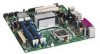
Intel Desktop Board DQ965GF Product Guide Installing and Removing the Desktop Board 30 Installing and Removing a Processor 31 Installing a Processor 31 Installing the Processor Fan Heat Sink 34 Connecting the Processor Fan Heat Sink Cable 34 Removing... Serial ATA (SATA) Cable 43 Connecting to Internal Headers 44 Installing a Front Panel Audio Solution for Intel® High Definition Audio 45 Connecting to the USB 2.0 Headers 46 Connecting to the Front Panel Header 46 Connecting to the Alternate Front Panel Power LED Header 47 Connecting to the IEEE 1394a Header 47 Connecting to the...
Intel Desktop Board DQ965GF Product Guide Installing and Removing the Desktop Board 30 Installing and Removing a Processor 31 Installing a Processor 31 Installing the Processor Fan Heat Sink 34 Connecting the Processor Fan Heat Sink Cable 34 Removing... Serial ATA (SATA) Cable 43 Connecting to Internal Headers 44 Installing a Front Panel Audio Solution for Intel® High Definition Audio 45 Connecting to the USB 2.0 Headers 46 Connecting to the Front Panel Header 46 Connecting to the Alternate Front Panel Power LED Header 47 Connecting to the IEEE 1394a Header 47 Connecting to the...
Product Guide
Page 7
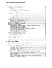
... 20. Internal Headers 44 23. Connecting Power Supply Cables 50 26. Original SATA Port Mapping for Desktop Board DQ965GF After RAID is Enabled 66 vii Desktop Board DQ965GF Mounting Screw Hole Locations 30 6. Lift the Load Plate 31 8. Dual Channel Memory Configuration Example 2... Installing the I/O Shield 29 5. Back Panel Connectors 54 29. Desktop Board DQ965GF Components 11 2. Remove the Protective Socket Cover 32 9. Location of Other Connectors and Headers 51 27. Lift Socket Lever 31 7. Back Panel Audio Connectors 48 24. Dual Channel Memory Configuration...
... 20. Internal Headers 44 23. Connecting Power Supply Cables 50 26. Original SATA Port Mapping for Desktop Board DQ965GF After RAID is Enabled 66 vii Desktop Board DQ965GF Mounting Screw Hole Locations 30 6. Lift the Load Plate 31 8. Dual Channel Memory Configuration Example 2... Installing the I/O Shield 29 5. Back Panel Connectors 54 29. Desktop Board DQ965GF Components 11 2. Remove the Protective Socket Cover 32 9. Location of Other Connectors and Headers 51 27. Lift Socket Lever 31 7. Back Panel Audio Connectors 48 24. Dual Channel Memory Configuration...
Product Guide
Page 8
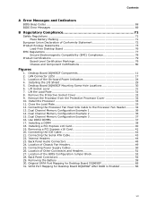
... 71 16. Front Panel Header 46 8. Desktop Board DQ965GF Components 12 3. Alternate Front Panel Power LED Header 47 9. IEEE 1394a Header Signal Names 47 10. Lead-Free Board Markings 76 17. LAN Connector LED States 17 4. Jumper Settings for Intel High Definition Audio 45 5. BIOS Error Messages 69 15. Feature Summary 9 2. Beep Codes 69 14. Intel Desktop Board DQ965GF Product Guide Tables...
... 71 16. Front Panel Header 46 8. Desktop Board DQ965GF Components 12 3. Alternate Front Panel Power LED Header 47 9. IEEE 1394a Header Signal Names 47 10. Lead-Free Board Markings 76 17. LAN Connector LED States 17 4. Jumper Settings for Intel High Definition Audio 45 5. BIOS Error Messages 69 15. Feature Summary 9 2. Beep Codes 69 14. Intel Desktop Board DQ965GF Product Guide Tables...
Product Guide
Page 9
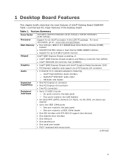
...of the desktop board. Table 1 summarizes the major features of Intel® Desktop Board DQ965GF. Feature Summary Form Factor Processor Main Memory Chipset Graphics Audio Expansion Capabilities Peripheral Interfaces microATX (243.84 millimeters [9.60 inches] x 243.84 millimeters [9.60 inches]) Support for up to 8 GB of system memory Intel®...(3.0 Gb/s), via the ICH8, one device per channel • Up to two IEEE 1394a ports ― One port routed to the back panel ― One port routed to a IEEE 1394a header • One IDE interface with ATA-66/100 support (two devices) • One ...
...of the desktop board. Table 1 summarizes the major features of Intel® Desktop Board DQ965GF. Feature Summary Form Factor Processor Main Memory Chipset Graphics Audio Expansion Capabilities Peripheral Interfaces microATX (243.84 millimeters [9.60 inches] x 243.84 millimeters [9.60 inches]) Support for up to 8 GB of system memory Intel®...(3.0 Gb/s), via the ICH8, one device per channel • Up to two IEEE 1394a ports ― One port routed to the back panel ― One port routed to a IEEE 1394a header • One IDE interface with ATA-66/100 support (two devices) • One ...
Product Guide
Page 12
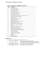
... Front panel header Serial ATA connectors Hi-speed USB 2.0 headers Speaker IDE connector IEEE 1394a header Related Links: Go to the following links for more information about: • Desktop Board DQ965GF • Supported processors • Audio software and utilities • LAN software and drivers http://www.intel.com/design/motherbd http://support.intel.com/support/motherboards/desktop http://support.intel...
... Front panel header Serial ATA connectors Hi-speed USB 2.0 headers Speaker IDE connector IEEE 1394a header Related Links: Go to the following links for more information about: • Desktop Board DQ965GF • Supported processors • Audio software and utilities • LAN software and drivers http://www.intel.com/design/motherbd http://support.intel.com/support/motherboards/desktop http://support.intel...
Product Guide
Page 16
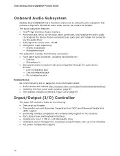
... Microphone in • Back panel audio connectors that includes a SigmaTel STAC9227 audio codec and an HD Audio Link header. Intel Desktop Board DQ965GF Product Guide Onboard Audio Subsystem Desktop Board DQ965GF has a flexible 6-channel (5.1) onboard audio subsystem that are configurable through the audio device drivers: ― Line ... pages for more information about: • Audio drivers and utilities http://support.intel.com/support/motherboards/desktop/ • Installing the front panel audio solution, page 45 • The location of audio connectors, Figure 23 on page 48 Input/...
... Microphone in • Back panel audio connectors that includes a SigmaTel STAC9227 audio codec and an HD Audio Link header. Intel Desktop Board DQ965GF Product Guide Onboard Audio Subsystem Desktop Board DQ965GF has a flexible 6-channel (5.1) onboard audio subsystem that are configurable through the audio device drivers: ― Line ... pages for more information about: • Audio drivers and utilities http://support.intel.com/support/motherboards/desktop/ • Installing the front panel audio solution, page 45 • The location of audio connectors, Figure 23 on page 48 Input/...
Product Guide
Page 27
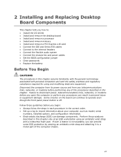
... can provide some ESD protection by wearing an antistatic wrist strap and attaching it to the internal headers • Connect the flexible audio system • Connect the chassis fan and power cables • Set the BIOS configuration jumper • Clear passwords •.... Failure to operate even though the front panel power button is not available, you can result in this chapter. 2 Installing and Replacing Desktop Board Components This chapter tells you how to: • Install the I/O shield • Install and remove the desktop board • Install and remove a processor &#...
... can provide some ESD protection by wearing an antistatic wrist strap and attaching it to the internal headers • Connect the flexible audio system • Connect the chassis fan and power cables • Set the BIOS configuration jumper • Clear passwords •.... Failure to operate even though the front panel power button is not available, you can result in this chapter. 2 Installing and Replacing Desktop Board Components This chapter tells you how to: • Install the I/O shield • Install and remove the desktop board • Install and remove a processor &#...
Product Guide
Page 44
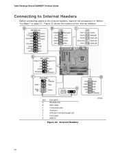
Item Description A HD Audio Link B IEEE 1394a C Front panel audio D Serial port E Alternate front panel power LED F Front panel G USB 2.0 Figure 22. Internal Headers 44 Figure 22 shows the location of the internal headers. Intel Desktop Board DQ965GF Product Guide Connecting to Internal Headers Before connecting cables to the internal headers, observe the precautions in "Before You Begin" on page 27.
Item Description A HD Audio Link B IEEE 1394a C Front panel audio D Serial port E Alternate front panel power LED F Front panel G USB 2.0 Figure 22. Internal Headers 44 Figure 22 shows the location of the internal headers. Intel Desktop Board DQ965GF Product Guide Connecting to Internal Headers Before connecting cables to the internal headers, observe the precautions in "Before You Begin" on page 27.

Product Guide
Page 45
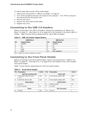
... 2 AUD_GND 3 MIC_BIAS 4 AUD_GND 5 FP_OUT_R 7 AUD_5V 9 FP_OUT_L 6 FP_RETURN_R 8 KEY 10 FP_RETURN_L 5. Turn off all peripheral devices connected to the computer. Installing and Replacing Desktop Board Components Installing a Front Panel Audio Solution for Intel High Definition Audio Pin Signal Name 1 PORT 1L 3 PORT 1R 5 PORT 2R 7 SENSE_SEND 9 PORT 2L Pin Signal Name 2 GND 4 PRESENCE# 6 SENSE1_RETURN 8 KEY (no pin...
... 2 AUD_GND 3 MIC_BIAS 4 AUD_GND 5 FP_OUT_R 7 AUD_5V 9 FP_OUT_L 6 FP_RETURN_R 8 KEY 10 FP_RETURN_L 5. Turn off all peripheral devices connected to the computer. Installing and Replacing Desktop Board Components Installing a Front Panel Audio Solution for Intel High Definition Audio Pin Signal Name 1 PORT 1L 3 PORT 1R 5 PORT 2R 7 SENSE_SEND 9 PORT 2L Pin Signal Name 2 GND 4 PRESENCE# 6 SENSE1_RETURN 8 KEY (no pin...
Product Guide
Page 46
...-up to the USB 2.0 headers, observe the precautions in "Before You Begin" on page 44 for each USB 2.0 header. Intel Desktop Board DQ965GF Product Guide To restore back panel audio, follow these steps: 1. See Figure 22, F on page 27. Remove the front panel audio cable. 5. USB Port B Signal Name POWER DD+ GND NO CONNECT Connecting to the Front...
...-up to the USB 2.0 headers, observe the precautions in "Before You Begin" on page 44 for each USB 2.0 header. Intel Desktop Board DQ965GF Product Guide To restore back panel audio, follow these steps: 1. See Figure 22, F on page 27. Remove the front panel audio cable. 5. USB Port B Signal Name POWER DD+ GND NO CONNECT Connecting to the Front...
Product Guide
Page 48
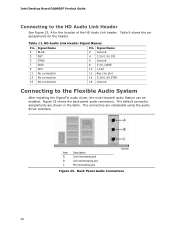
...of the HD Audio Link header. Table 11. Figure 23 shows the back panel audio connectors. Back Panel Audio Connectors 48 Intel Desktop Board DQ965GF Product Guide Connecting to the Flexible Audio System After installing the SigmaTel audio driver, the multi-channel audio feature can be enabled. HD Audio Link Header ...14 3.3V/1.5V STBY 15 No connection 16 Ground Connecting to the HD Audio Link Header See Figure 22, A for the header. The default connector assignments are retaskable using the audio driver interface. The connectors are shown in /retasking jack Figure 23. ...
...of the HD Audio Link header. Table 11. Figure 23 shows the back panel audio connectors. Back Panel Audio Connectors 48 Intel Desktop Board DQ965GF Product Guide Connecting to the Flexible Audio System After installing the SigmaTel audio driver, the multi-channel audio feature can be enabled. HD Audio Link Header ...14 3.3V/1.5V STBY 15 No connection 16 Ground Connecting to the HD Audio Link Header See Figure 22, A for the header. The default connector assignments are retaskable using the audio driver interface. The connectors are shown in /retasking jack Figure 23. ...

Product Guide
Page 54
Back Panel Connectors 54 Intel Desktop Board DQ965GF Product Guide Back Panel Connectors NOTE The line out connector, located on the back panel, is designed to this output. Figure 28 shows the back panel connectors. Poor audio quality may occur if passive (nonamplified) speakers are connected to power either headphones or amplified speakers only. Figure 28.
Back Panel Connectors 54 Intel Desktop Board DQ965GF Product Guide Back Panel Connectors NOTE The line out connector, located on the back panel, is designed to this output. Figure 28 shows the back panel connectors. Poor audio quality may occur if passive (nonamplified) speakers are connected to power either headphones or amplified speakers only. Figure 28.

