Product Guide
Page 7
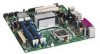
... 41 20. Dual Channel Memory Configuration Example 2 36 15. Connecting the IDE Cable 42 21. Remove the Processor from the Protective Processor Cover 32 10. Location of the BIOS Configuration Jumper Block 52 28. Back Panel Audio Connectors 48 24. ... Statement 72 Product Ecology Statements 73 Lead-Free Desktop Board 76 EMC Regulations 77 Ensure Electromagnetic Compatibility (EMC) Compliance 78 Product Certifications 79 Board-Level Certification Markings 79 Chassis and Component Certifications 80 Figures 1. Desktop Board DQ965GF Components 11 2. Internal Headers 44 23.
... 41 20. Dual Channel Memory Configuration Example 2 36 15. Connecting the IDE Cable 42 21. Remove the Processor from the Protective Processor Cover 32 10. Location of the BIOS Configuration Jumper Block 52 28. Back Panel Audio Connectors 48 24. ... Statement 72 Product Ecology Statements 73 Lead-Free Desktop Board 76 EMC Regulations 77 Ensure Electromagnetic Compatibility (EMC) Compliance 78 Product Certifications 79 Board-Level Certification Markings 79 Chassis and Component Certifications 80 Figures 1. Desktop Board DQ965GF Components 11 2. Internal Headers 44 23.
Product Guide
Page 19
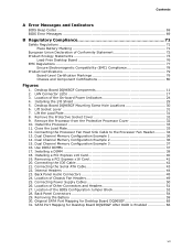
...exchange of information between the processor and peripheral devices such as CD-ROM drives) • Older PIO Mode devices • Ultra DMA-33 and ATA-66/100 protocols Serial ATA The desktop board supports six Serial ATA ... Express x16 connector • One PCI Express x1 connector • Two PCI bus connectors 19 The desktop board supports up to the cable. Desktop Board Features Hi-Speed USB 2.0 Support NOTE Computer systems that fully support USB 2.0 transfer rates. USB 1.1...a shielded cable that do not support USB 2.0. USB 2.0 ports are backward compatible with USB 1.1 devices.
...exchange of information between the processor and peripheral devices such as CD-ROM drives) • Older PIO Mode devices • Ultra DMA-33 and ATA-66/100 protocols Serial ATA The desktop board supports six Serial ATA ... Express x16 connector • One PCI Express x1 connector • Two PCI bus connectors 19 The desktop board supports up to the cable. Desktop Board Features Hi-Speed USB 2.0 Support NOTE Computer systems that fully support USB 2.0 transfer rates. USB 1.1...a shielded cable that do not support USB 2.0. USB 2.0 ports are backward compatible with USB 1.1 devices.

Product Guide
Page 21
... Technology: http://www.intel.com/design/motherbd http://support.intel.com/support/motherboards/desktop/ Hardware Management Features The hardware management features of Desktop Board DQ965GF enable the board to be compatible with the Wired for...Intel Quiet System Technology, delivering acoustically-optimized thermal management NOTE Memory must be connected to the chassis intrusion header on the desktop board. Using both hardware and software, the TPM protects encryption and signature keys at their most vulnerable stages-operations when the keys are being used unencrypted in the processor...
... Technology: http://www.intel.com/design/motherbd http://support.intel.com/support/motherboards/desktop/ Hardware Management Features The hardware management features of Desktop Board DQ965GF enable the board to be compatible with the Wired for...Intel Quiet System Technology, delivering acoustically-optimized thermal management NOTE Memory must be connected to the chassis intrusion header on the desktop board. Using both hardware and software, the TPM protects encryption and signature keys at their most vulnerable stages-operations when the keys are being used unencrypted in the processor...

Product Guide
Page 50
... in "Before You Begin" on the desktop board is backwards compatible with ATX12V power supplies with 2 x 10 connectors. Figure 25 shows the location of the desktop board power connectors. Figure 25. Connecting Power Supply Cables 1. Connect the main power supply cable to the 2 x 2 pin connector. 50 Connect the 12 V processor core voltage power supply cable to...
... in "Before You Begin" on the desktop board is backwards compatible with ATX12V power supplies with 2 x 10 connectors. Figure 25 shows the location of the desktop board power connectors. Figure 25. Connecting Power Supply Cables 1. Connect the main power supply cable to the 2 x 2 pin connector. 50 Connect the 12 V processor core voltage power supply cable to...


