
Product Guide
Page 7
...to BIOS Button 20 4. Installing a PCI Express x16 Graphics Card 43 21. Contents A Error Messages and Indicators BIOS Error Codes 71 BIOS Error Messages 72 Port 80h POST Codes 73 B Regulatory Compliance Safety Standards 77 Battery Caution 77 European Union Declaration of Conformity Statement 78... Configuration with Two DIMMs 38 16. Installing the I/O Shield 31 8. Removing a PCI Express x16 Graphics Card 44 22. Install the Processor 35 13. Connecting the Serial ATA Cables 46 24. Intel Desktop Board DP67BG Mounting Screw Hole Locations 32 9. LAN Connector LEDs 17 3....
...to BIOS Button 20 4. Installing a PCI Express x16 Graphics Card 43 21. Contents A Error Messages and Indicators BIOS Error Codes 71 BIOS Error Messages 72 Port 80h POST Codes 73 B Regulatory Compliance Safety Standards 77 Battery Caution 77 European Union Declaration of Conformity Statement 78... Configuration with Two DIMMs 38 16. Installing the I/O Shield 31 8. Removing a PCI Express x16 Graphics Card 44 22. Install the Processor 35 13. Connecting the Serial ATA Cables 46 24. Intel Desktop Board DP67BG Mounting Screw Hole Locations 32 9. LAN Connector LEDs 17 3....
Product Guide
Page 8
Installing the WiFi/Bluetooth Module 64 31. Intel Desktop Board DP67BG Components 13 3. Diagnostic LEDs 26 6. Front-panel Power LED Blink Codes 71 18. Port 80h POST Codes 73 20. POST Code LED Display 73 32. Audio Jack Retasking Support 16 4. LAN Connector LEDs 17 5. S/PDIF Header Signal ...Front Panel Header Signal Names 51 14. BIOS Error Messages 72 19. Location of the Chassis Fan Headers 53 27. EMC Regulations 83 22. Location of the BIOS Configuration Jumper Block 55 29. Intel Desktop Board DP67BG China RoHS Material Self Declaration Table 82 Tables ...
Installing the WiFi/Bluetooth Module 64 31. Intel Desktop Board DP67BG Components 13 3. Diagnostic LEDs 26 6. Front-panel Power LED Blink Codes 71 18. Port 80h POST Codes 73 20. POST Code LED Display 73 32. Audio Jack Retasking Support 16 4. LAN Connector LEDs 17 5. S/PDIF Header Signal ...Front Panel Header Signal Names 51 14. BIOS Error Messages 72 19. Location of the Chassis Fan Headers 53 27. EMC Regulations 83 22. Location of the BIOS Configuration Jumper Block 55 29. Intel Desktop Board DP67BG China RoHS Material Self Declaration Table 82 Tables ...
Product Guide
Page 73
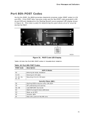
... code is left at port 80h and displayed on the Desktop Board's seven-segment LED display shown in hexadecimal notation. POST Code LED Display Table 19 lists the Port 80h POST codes in Figure 31. Error Messages and Indicators Port 80h POST Codes During the POST, the BIOS generates diagnostic progress codes (POST codes) to I/O port 80h. Figure 31...
... code is left at port 80h and displayed on the Desktop Board's seven-segment LED display shown in hexadecimal notation. POST Code LED Display Table 19 lists the Port 80h POST codes in Figure 31. Error Messages and Indicators Port 80h POST Codes During the POST, the BIOS generates diagnostic progress codes (POST codes) to I/O port 80h. Figure 31...
Product Guide
Page 74
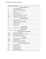
Intel Desktop Board DP67BG Product Guide POST Code 11 12 13 14 15 16 17, 18 19, 1A 1B, 1C 21 23 24 27 28 29 2A, 2B 31, 33, 34 41-43 44-46 47-4C 4D-4F 50-52 58, 59 5A, 5B 5F 60-6F E4 E7 E8 E9 EB Description ... to end CPU DXE SMM phase begin to end I/O Buses PCI enumeration, allocation, hot plug Resetting USB bus Resetting SATA bus and all devices Unrecoverable error, start with PIC Boot Device Selection (BDS) BDS driver entry Entered DXE phase Waiting for user input Checking password Entering BIOS setup Calling legacy option...
Intel Desktop Board DP67BG Product Guide POST Code 11 12 13 14 15 16 17, 18 19, 1A 1B, 1C 21 23 24 27 28 29 2A, 2B 31, 33, 34 41-43 44-46 47-4C 4D-4F 50-52 58, 59 5A, 5B 5F 60-6F E4 E7 E8 E9 EB Description ... to end CPU DXE SMM phase begin to end I/O Buses PCI enumeration, allocation, hot plug Resetting USB bus Resetting SATA bus and all devices Unrecoverable error, start with PIC Boot Device Selection (BDS) BDS driver entry Entered DXE phase Waiting for user input Checking password Entering BIOS setup Calling legacy option...
Product Specification
Page 8
... 65 31. BIOS Setup Configuration Jumper Settings 53 24. AcceptableDrives/Media Types for a Two-Color Power LED 50 23. EMC Regulations 83 32H 41. Front Panel Header 49 21. BIOS Setup Program Function Keys 62 30. BIOS Beep Codes 71 34. Port 80h POST Code Ranges 73...26. BIOS Error Messages 72 36. Safety Standards 79 40. Thermal Considerations for a One-Color Power LED 50 22. Front-panel Power LED Blink Codes 72 35. BIOS Setup Program Menu Bar 62 29. Regulatory Compliance Marks 87 14H 324H viii Intel Desktop Board DP67BG Technical Product ...
... 65 31. BIOS Setup Configuration Jumper Settings 53 24. AcceptableDrives/Media Types for a Two-Color Power LED 50 23. EMC Regulations 83 32H 41. Front Panel Header 49 21. BIOS Setup Program Function Keys 62 30. BIOS Beep Codes 71 34. Port 80h POST Code Ranges 73...26. BIOS Error Messages 72 36. Safety Standards 79 40. Thermal Considerations for a One-Color Power LED 50 22. Front-panel Power LED Blink Codes 72 35. BIOS Setup Program Menu Bar 62 29. Regulatory Compliance Marks 87 14H 324H viii Intel Desktop Board DP67BG Technical Product ...


