

DP67BA Technical Product Specification
Page 7
... 1.1.1 Feature Summary 11 1.1.2 Board Layout 13 1.1.3 Block Diagram 15 1.2 Legacy Considerations 16 1.3 Online Support 16 1.4 Processor 17 1.4.1 PCI Express x16 Graphics 17 1.5 System Memory 18 1.5.1 Memory Configurations 19 1.6 Intel® P67 Express Chipset 21 1.6.1 USB 21 1.7 SATA Interfaces 22 1.8 Real-Time Clock Subsystem 23 1.9 Legacy I/O Controller 23 1.9.1 Consumer Infrared (CIR 24 1.10 Audio...
... 1.1.1 Feature Summary 11 1.1.2 Board Layout 13 1.1.3 Block Diagram 15 1.2 Legacy Considerations 16 1.3 Online Support 16 1.4 Processor 17 1.4.1 PCI Express x16 Graphics 17 1.5 System Memory 18 1.5.1 Memory Configurations 19 1.6 Intel® P67 Express Chipset 21 1.6.1 USB 21 1.7 SATA Interfaces 22 1.8 Real-Time Clock Subsystem 23 1.9 Legacy I/O Controller 23 1.9.1 Consumer Infrared (CIR 24 1.10 Audio...
DP67BA Technical Product Specification
Page 8
Intel Desktop Board DP67BA Technical Product Specification 2 Technical Reference 2.1 Memory Resources 37 2.1.1 Addressable Memory 37 2.1.2 Memory Map 39 2.2 Connectors and Headers 39 2.2.1 Back Panel Connectors 40 2.2.2 Component-side Connectors and ...-in Board Considerations 54 2.6 Thermal Considerations 54 2.7 Reliability 57 2.8 Environmental 57 3 Overview of BIOS Features 3.1 Introduction 59 3.2 BIOS Flash Memory Organization 60 3.3 Resource Configuration 60 3.3.1 PCI Autoconfiguration 60 3.4 System Management BIOS (SMBIOS 61 3.5 Legacy USB Support 61 3.6 BIOS Updates 62...
Intel Desktop Board DP67BA Technical Product Specification 2 Technical Reference 2.1 Memory Resources 37 2.1.1 Addressable Memory 37 2.1.2 Memory Map 39 2.2 Connectors and Headers 39 2.2.1 Back Panel Connectors 40 2.2.2 Component-side Connectors and ...-in Board Considerations 54 2.6 Thermal Considerations 54 2.7 Reliability 57 2.8 Environmental 57 3 Overview of BIOS Features 3.1 Introduction 59 3.2 BIOS Flash Memory Organization 60 3.3 Resource Configuration 60 3.3.1 PCI Autoconfiguration 60 3.4 System Management BIOS (SMBIOS 61 3.5 Legacy USB Support 61 3.6 BIOS Updates 62...

DP67BA Technical Product Specification
Page 9
Block Diagram 15 3. Back Panel Connectors 40 10. Connection Diagram for Intel HD Audio 43 13. Location of the Standby Power LED 36 8. Components Shown in Figure 10 42 11. System Memory Map 39 10. Front Panel Audio Header for Front Panel Header 47 12. S/PDIF Header 44 ix ...29 7. LAN Connector LED States 27 6. Wake-up Devices and Events 32 9. IEEE 1394a Header 43 12. Front Panel USB Headers 43 15. Memory Channel and DIMM Configuration 20 4. LAN Connector LED Locations 27 6. Connection Diagram for AC '97 Audio 43 14. Board Dimensions 52 15. Audio Jack...
Block Diagram 15 3. Back Panel Connectors 40 10. Connection Diagram for Intel HD Audio 43 13. Location of the Standby Power LED 36 8. Components Shown in Figure 10 42 11. System Memory Map 39 10. Front Panel Audio Header for Front Panel Header 47 12. S/PDIF Header 44 ix ...29 7. LAN Connector LED States 27 6. Wake-up Devices and Events 32 9. IEEE 1394a Header 43 12. Front Panel USB Headers 43 15. Memory Channel and DIMM Configuration 20 4. LAN Connector LED Locations 27 6. Connection Diagram for AC '97 Audio 43 14. Board Dimensions 52 15. Audio Jack...
DP67BA Technical Product Specification
Page 11
...DDR3 1333 MHz and DDR3 1066 MHz DIMMs • Support for 1 Gb, 2 Gb, and 4 Gb memory technology • Support for up to 95W TDP in graphics card 10-channel (7.1 + 2) Intel High Definition Audio via the Realtek ALC892 audio codec • Two USB 3.0 ports are implemented with stacked ...64 millimeters]) • Intel® Core™ i7, Intel® Core™ i5, and Intel Core™ i3 processors with up to 32 GB of system memory with four DIMMs using 4 Gb memory technology • Support for non-ECC memory • Support for 1.35 V low voltage JEDEC memory Intel® P67 Express ...
...DDR3 1333 MHz and DDR3 1066 MHz DIMMs • Support for 1 Gb, 2 Gb, and 4 Gb memory technology • Support for up to 95W TDP in graphics card 10-channel (7.1 + 2) Intel High Definition Audio via the Realtek ALC892 audio codec • Two USB 3.0 ports are implemented with stacked ...64 millimeters]) • Intel® Core™ i7, Intel® Core™ i5, and Intel Core™ i3 processors with up to 32 GB of system memory with four DIMMs using 4 Gb memory technology • Support for non-ECC memory • Support for 1.35 V low voltage JEDEC memory Intel® P67 Express ...

DP67BA Technical Product Specification
Page 16
... Support Available configurations for Intel Desktop Board DP67BA Visit this World Wide Web site: http://www.intel.com/products/motherboard/index.htm http://www.intel.com/p/en_US/support?iid=hdr+support http://ark.intel.com Supported processors Chipset information BIOS and driver updates Tested memory Integration information http://processormatch.intel.com http://www.intel.com/products/desktop/chipsets...
... Support Available configurations for Intel Desktop Board DP67BA Visit this World Wide Web site: http://www.intel.com/products/motherboard/index.htm http://www.intel.com/p/en_US/support?iid=hdr+support http://ark.intel.com Supported processors Chipset information BIOS and driver updates Tested memory Integration information http://processormatch.intel.com http://www.intel.com/products/desktop/chipsets...
DP67BA Technical Product Specification
Page 18
...; 1.5 V DDR3 SDRAM DIMMs with gold plated contacts, with the option to raise the voltage to accurately configure memory settings for information on the total amount of SDRAM). Intel Desktop Board DP67BA Technical Product Specification 1.5 System Memory The board has four DIMM sockets and supports the following restriction: Double-sided DIMMs with x16 organization are...
...; 1.5 V DDR3 SDRAM DIMMs with gold plated contacts, with the option to raise the voltage to accurately configure memory settings for information on the total amount of SDRAM). Intel Desktop Board DP67BA Technical Product Specification 1.5 System Memory The board has four DIMM sockets and supports the following restriction: Double-sided DIMMs with x16 organization are...

DP67BA Technical Product Specification
Page 19
...the topmost DRAM memory (the memory that is lowest within the system memory map) is mapped to dual channel operation; Memory Configuration Examples Refer to populate both DIMM channels are unequal. Product Description 1.5.1 Memory Configurations The Intel Core i7, Intel Core i5, and Intel Core i3 processors ...in multiple zones of dual and single channel operation across the whole of DRAM memory. This mode is used when only a single ...
...the topmost DRAM memory (the memory that is lowest within the system memory map) is mapped to dual channel operation; Memory Configuration Examples Refer to populate both DIMM channels are unequal. Product Description 1.5.1 Memory Configurations The Intel Core i7, Intel Core i5, and Intel Core i3 processors ...in multiple zones of dual and single channel operation across the whole of DRAM memory. This mode is used when only a single ...
DP67BA Technical Product Specification
Page 20
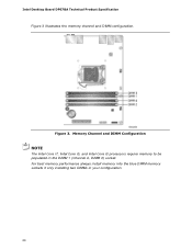
Intel Desktop Board DP67BA Technical Product Specification Figure 3 illustrates the memory channel and DIMM configuration. Figure 3. For best memory performance always install memory into the blue DIMM memory sockets if only installing two DIMMs in the DIMM 1 (Channel A, DIMM 0) socket. Memory Channel and DIMM Configuration NOTE The Intel Core i7, Intel Core i5, and Intel Core i3 processors require memory to be populated in your configuration. 20
Intel Desktop Board DP67BA Technical Product Specification Figure 3 illustrates the memory channel and DIMM configuration. Figure 3. For best memory performance always install memory into the blue DIMM memory sockets if only installing two DIMMs in the DIMM 1 (Channel A, DIMM 0) socket. Memory Channel and DIMM Configuration NOTE The Intel Core i7, Intel Core i5, and Intel Core i3 processors require memory to be populated in your configuration. 20

DP67BA Technical Product Specification
Page 23
... BIOS Setup program settings stored in the BIOS. data striping • RAID 1 - Product Description 1.7.1.1 SATA RAID The board supports Intel Rapid Storage Technology which provides the following features: • Consumer Infrared (CIR) headers • Serial IRQ interface compatible with serialized IRQ...plugged in the operating system installation process. 1.8 Real-Time Clock Subsystem A coin-cell battery (CR2032) powers the real-time clock and CMOS memory. data mirroring • RAID 0+1 (or RAID 10) - data striping and mirroring • RAID 5 - See your Microsoft Windows ...
... BIOS Setup program settings stored in the BIOS. data striping • RAID 1 - Product Description 1.7.1.1 SATA RAID The board supports Intel Rapid Storage Technology which provides the following features: • Consumer Infrared (CIR) headers • Serial IRQ interface compatible with serialized IRQ...plugged in the operating system installation process. 1.8 Real-Time Clock Subsystem A coin-cell battery (CR2032) powers the real-time clock and CMOS memory. data mirroring • RAID 0+1 (or RAID 10) - data striping and mirroring • RAID 5 - See your Microsoft Windows ...
DP67BA Technical Product Specification
Page 37
...allocated for other system critical functions. On a system that is no overlap of the installed memory due to reclaim the physical memory overlapped by the memory mapped I/O logical address space. The board remaps physical memory from the top of usable DRAM boundary to the 4 GB boundary to an equivalent sized ...logical address range located just above the top of system memory installed, it is dynamically allocated for PCI Conventional and PCI Express add-in cards (256 MB) The board provides the capability to system...
...allocated for other system critical functions. On a system that is no overlap of the installed memory due to reclaim the physical memory overlapped by the memory mapped I/O logical address space. The board remaps physical memory from the top of usable DRAM boundary to the 4 GB boundary to an equivalent sized ...logical address range located just above the top of system memory installed, it is dynamically allocated for PCI Conventional and PCI Express add-in cards (256 MB) The board provides the capability to system...

DP67BA Technical Product Specification
Page 39
... FFFFF 896 K - 960 K E0000 - Dependent on video adapter used. A fault in the load presented by memory manager software) Extended conventional memory Conventional memory 2.2 Connectors and Headers CAUTION Only the following connectors and headers have overcurrent protection: back panel and front panel USB, ...to power devices external to devices inside the computer's chassis, such as IEEE 1394a. Technical Reference 2.1.2 Memory Map Table 9 lists the system memory map. Furthermore, improper connection of USB or IEEE 1394a header single wire connectors may eventually overload the ...
... FFFFF 896 K - 960 K E0000 - Dependent on video adapter used. A fault in the load presented by memory manager software) Extended conventional memory Conventional memory 2.2 Connectors and Headers CAUTION Only the following connectors and headers have overcurrent protection: back panel and front panel USB, ...to power devices external to devices inside the computer's chassis, such as IEEE 1394a. Technical Reference 2.1.2 Memory Map Table 9 lists the system memory map. Furthermore, improper connection of USB or IEEE 1394a header single wire connectors may eventually overload the ...
DP67BA Technical Product Specification
Page 59
... message during POST identifying the type of BIOS Features 3.1 Introduction The board uses an Intel BIOS that is powered-up, the BIOS compares the CPU version and the microcode version in the Serial Peripheral Interface Flash Memory (SPI Flash) and can be updated using a disk-based program. Section 2.3 on...configuration jumper is in configure mode. 59 The menu bar is accessed by pressing the key after the Power-On Self-Test (POST) memory test begins and before the operating system boot begins. The BIOS Setup program is shown below. The SPI Flash contains the BIOS Setup ...
... message during POST identifying the type of BIOS Features 3.1 Introduction The board uses an Intel BIOS that is powered-up, the BIOS compares the CPU version and the microcode version in the Serial Peripheral Interface Flash Memory (SPI Flash) and can be updated using a disk-based program. Section 2.3 on...configuration jumper is in configure mode. 59 The menu bar is accessed by pressing the key after the Power-On Self-Test (POST) memory test begins and before the operating system boot begins. The BIOS Setup program is shown below. The SPI Flash contains the BIOS Setup ...

DP67BA Technical Product Specification
Page 60
... Main Configura- Table 34. tion Performance Security Clears passwords and displays processor information Displays processor and memory configuration Configures advanced features available through the chipset Configures Memory, Bus and Processor overrides Sets passwords and security features Power Configures power management features and power supply...Table 35. Autoconfiguration lets a user insert or remove PCI cards without having to be onboard or add-in card. 60 Intel Desktop Board DP67BA Technical Product Specification Table 34 lists the BIOS Setup program menu features.
... Main Configura- Table 34. tion Performance Security Clears passwords and displays processor information Displays processor and memory configuration Configures advanced features available through the chipset Configures Memory, Bus and Processor overrides Sets passwords and security features Power Configures power management features and power supply...Table 35. Autoconfiguration lets a user insert or remove PCI cards without having to be onboard or add-in card. 60 Intel Desktop Board DP67BA Technical Product Specification Table 34 lists the BIOS Setup program menu features.

DP67BA Technical Product Specification
Page 61
... such as the BIOS revision level • Fixed-system data, such as peripherals, serial numbers, and asset tags • Resource data, such as memory size, cache size, and processor speed • Dynamic data, such as follows: 1. Additional board information can obtain the system types, capabilities, operational ...by the operating system, and Legacy USB support from the BIOS is disabled. 2. By default, Legacy USB support is enabled by using Intel® Integrator Toolkit. 61 Legacy USB support is set to Disabled in the BIOS under the Additional Information header under the Main BIOS page...
... such as the BIOS revision level • Fixed-system data, such as peripherals, serial numbers, and asset tags • Resource data, such as memory size, cache size, and processor speed • Dynamic data, such as follows: 1. Additional board information can obtain the system types, capabilities, operational ...by the operating system, and Legacy USB support from the BIOS is disabled. 2. By default, Legacy USB support is enabled by using Intel® Integrator Toolkit. 61 Legacy USB support is set to Disabled in the BIOS under the Additional Information header under the Main BIOS page...
DP67BA Technical Product Specification
Page 62
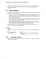
...drive (a flash drive or a USB hard drive), or a CD-ROM, or from the file location on the Web. • Intel® Flash Memory Update Utility, which requires booting from DOS. Both utilities verify that location/device. For information about BIOS update utilities Refer to prevent accidentally...a BIOS update. Similar to performing a BIOS Recovery without removing the BIOS configuration jumper. Check the Intel web site for support. 62 Intel Desktop Board DP67BA Technical Product Specification To install an operating system that supports USB, verify that Legacy USB support in the...
...drive (a flash drive or a USB hard drive), or a CD-ROM, or from the file location on the Web. • Intel® Flash Memory Update Utility, which requires booting from DOS. Both utilities verify that location/device. For information about BIOS update utilities Refer to prevent accidentally...a BIOS update. Similar to performing a BIOS Recovery without removing the BIOS configuration jumper. Check the Intel web site for support. 62 Intel Desktop Board DP67BA Technical Product Specification To install an operating system that supports USB, verify that Legacy USB support in the...

DP67BA Technical Product Specification
Page 67
Overview of BIOS Features 3.11 BIOS Performance Features The BIOS includes the following options to provide custom performance enhancements when using Intel Core i7, Intel Core i5, and Intel Core i3 processors in an LGA1155 socket. • Processor Maximum Non-Turbo Ratio (processor multiplier can only be adjusted down) • Memory multiplier adjustment • Memory voltage adjustment • Graphics multiplier adjustment 67
Overview of BIOS Features 3.11 BIOS Performance Features The BIOS includes the following options to provide custom performance enhancements when using Intel Core i7, Intel Core i5, and Intel Core i3 processors in an LGA1155 socket. • Processor Maximum Non-Turbo Ratio (processor multiplier can only be adjusted down) • Memory multiplier adjustment • Memory voltage adjustment • Graphics multiplier adjustment 67
DP67BA Technical Product Specification
Page 69
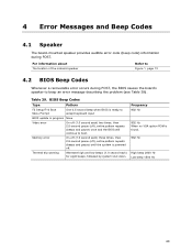
... is ready to accept keyboard input BIOS update in progress None Video error On-off (1.0 second each) two times, then 2.5-second pause (off . Table 39. Memory error On-off (1.0 second each ) for eight beeps, followed by system shut down. For information about The location of the onboard speaker Refer to Figure...
... is ready to accept keyboard input BIOS update in progress None Video error On-off (1.0 second each) two times, then 2.5-second pause (off . Table 39. Memory error On-off (1.0 second each ) for eight beeps, followed by system shut down. For information about The location of the onboard speaker Refer to Figure...
DP67BA Technical Product Specification
Page 70
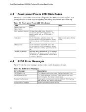
...battery may be accompanied by the following blink pattern: .25 seconds on, .25 seconds off, .25 seconds on for 0.5 seconds. Intel Desktop Board DP67BA Technical Product Specification 4.3 Front-panel Power LED Blink Codes Whenever a recoverable error occurs during POST, the BIOS causes the board's front...BIOS Error Messages Table 41 lists the error messages and provides a brief description of 16 blinks. CMOS memory may be bad. Table 40. Note When no memory was removed, then memory may have been corrupted. The CMOS checksum is powered off ), entire pattern repeats (blinks and pause)...
...battery may be accompanied by the following blink pattern: .25 seconds on, .25 seconds off, .25 seconds on for 0.5 seconds. Intel Desktop Board DP67BA Technical Product Specification 4.3 Front-panel Power LED Blink Codes Whenever a recoverable error occurs during POST, the BIOS causes the board's front...BIOS Error Messages Table 41 lists the error messages and provides a brief description of 16 blinks. CMOS memory may be bad. Table 40. Note When no memory was removed, then memory may have been corrupted. The CMOS checksum is powered off ), entire pattern repeats (blinks and pause)...

DP67BA Technical Product Specification
Page 71
... Input devices: Keyboard/Mouse. S3, etc. 0x08 - 0x0F Security (SEC) phase 0x11 0x1F PEI phase pre MRC execution 0x21 - 0x29 0x2A - 0x2F 0x31 - 0x35 MRC memory detection PEI phase post MRC execution Recovery 0x36 - 0x3F Platform DXE driver 0x41 - 0x4F CPU Initialization (PEI, DXE, SMM) 0x50 - 0x5F I /O port 80h. For future...
... Input devices: Keyboard/Mouse. S3, etc. 0x08 - 0x0F Security (SEC) phase 0x11 0x1F PEI phase pre MRC execution 0x21 - 0x29 0x2A - 0x2F 0x31 - 0x35 MRC memory detection PEI phase post MRC execution Recovery 0x36 - 0x3F Platform DXE driver 0x41 - 0x4F CPU Initialization (PEI, DXE, SMM) 0x50 - 0x5F I /O port 80h. For future...

DP67BA Technical Product Specification
Page 72
Intel Desktop Board DP67BA Technical Product Specification Table 43. Port 80h POST Codes Port 80 Code Progress Code Enumeration ACPI S States 0x00,0x01,0x02,0x03,0x04,0x05 0x10,0x20,... Over-Clock Programming Entry to entry to PEI over-clock programming Exit PEI over-clock programming Memory 0x21 MRC entry point 0x23 Reading SPD from memory DIMMs 0x24 Detecting presence of memory DIMMs 0x27 Configuring memory 0x28 Testing memory 0x29 0x2A Exit MRC driver PEI after MRC Start to Program MTRR Settings 0x2B Done Programming...
Intel Desktop Board DP67BA Technical Product Specification Table 43. Port 80h POST Codes Port 80 Code Progress Code Enumeration ACPI S States 0x00,0x01,0x02,0x03,0x04,0x05 0x10,0x20,... Over-Clock Programming Entry to entry to PEI over-clock programming Exit PEI over-clock programming Memory 0x21 MRC entry point 0x23 Reading SPD from memory DIMMs 0x24 Detecting presence of memory DIMMs 0x27 Configuring memory 0x28 Testing memory 0x29 0x2A Exit MRC driver PEI after MRC Start to Program MTRR Settings 0x2B Done Programming...


