
Product Guide
Page 5
... Features Supported Operating Systems 11 Desktop Board Components 12 Processor ...14 Main Memory...15 Intel® P55 Express Chipset 16 Audio Subsystem 16 LAN Subsystem 16 USB 2.0 Support 17 Serial ATA Support 17 Legacy I/O ...19 Expandability...19 BIOS ...19 Serial ATA Auto ... Indicator 23 Wake from USB 24 PME# Signal Wake-up Support 24 WAKE# Signal Wake-up Support 24 Wake from Consumer IR 24 ENERGY STAR*, e-Standby, and EuP Compliance 24 Onboard Power Button 25 Processor and Voltage Regulator LEDs 26 Back to BIOS Button 27 Speaker...28 Battery ...28 Real-Time...
... Features Supported Operating Systems 11 Desktop Board Components 12 Processor ...14 Main Memory...15 Intel® P55 Express Chipset 16 Audio Subsystem 16 LAN Subsystem 16 USB 2.0 Support 17 Serial ATA Support 17 Legacy I/O ...19 Expandability...19 BIOS ...19 Serial ATA Auto ... Indicator 23 Wake from USB 24 PME# Signal Wake-up Support 24 WAKE# Signal Wake-up Support 24 Wake from Consumer IR 24 ENERGY STAR*, e-Standby, and EuP Compliance 24 Onboard Power Button 25 Processor and Voltage Regulator LEDs 26 Back to BIOS Button 27 Speaker...28 Battery ...28 Real-Time...

Product Guide
Page 7
Location of the Processor and Voltage Regulator LEDs 26 7. Location of the Standby Power Indicator 23 5. Lift the Load Plate 34 12. Installing a DIMM 42 23. Internal Headers 48 vii SATA Drive Activity LED 18 4. Onboard Power Button ... Ecology Statements 79 Recycling Considerations 79 Lead-free 2LI/Pb-free 2LI Board 82 Restriction of the Back to the Processor Fan Header 38 18. Intel Desktop Board DP55WG Mounting Screw Hole Locations 32 10. Lower the Load Plate 37 16. Example Dual Channel Memory Configuration with Four DIMMs 40 20. Use DDR3...
Location of the Processor and Voltage Regulator LEDs 26 7. Location of the Standby Power Indicator 23 5. Lift the Load Plate 34 12. Installing a DIMM 42 23. Internal Headers 48 vii SATA Drive Activity LED 18 4. Onboard Power Button ... Ecology Statements 79 Recycling Considerations 79 Lead-free 2LI/Pb-free 2LI Board 82 Restriction of the Back to the Processor Fan Header 38 18. Intel Desktop Board DP55WG Mounting Screw Hole Locations 32 10. Lower the Load Plate 37 16. Example Dual Channel Memory Configuration with Four DIMMs 40 20. Use DDR3...
Product Guide
Page 13
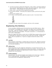
... 12 V processor core voltage connector (2 x 4 pin) Processor fan header Processor LED Voltage regulator LED Processor socket POST code LED display DDR3 Channel A, DIMM 0 and DIMM 1 sockets DDR3 Channel B, DIMM 0 and DIMM 1 sockets Onboard power button Standby power indicator LED Main... (2) IEEE 1394a header BIOS configuration jumper block Serial ATA connectors Chassis intrusion header USB 2.0 header Speaker Auxiliary PCI Express graphics power connector (SATA-style) 13 Intel Desktop Board DP55WG Components Label A B C D E F G H I J K L M N O P Q R S T U V W X Y Z AA BB CC DD EE FF GG ...
... 12 V processor core voltage connector (2 x 4 pin) Processor fan header Processor LED Voltage regulator LED Processor socket POST code LED display DDR3 Channel A, DIMM 0 and DIMM 1 sockets DDR3 Channel B, DIMM 0 and DIMM 1 sockets Onboard power button Standby power indicator LED Main... (2) IEEE 1394a header BIOS configuration jumper block Serial ATA connectors Chassis intrusion header USB 2.0 header Speaker Auxiliary PCI Express graphics power connector (SATA-style) 13 Intel Desktop Board DP55WG Components Label A B C D E F G H I J K L M N O P Q R S T U V W X Y Z AA BB CC DD EE FF GG ...

Product Guide
Page 21
...V standby power indicator LED • Wake from USB • Power Management Event signal (PME#) wakeup support • WAKE# signal wake-up support • Wake from an AC power failure, the computer returns to the power state it was in the BIOS Setup program's Boot menu. Desktop Board...feature that provides full ACPI support. Power Management Power management is implemented at several levels, including software support through system control. The Desktop Board has three power connectors. The security feature uses a mechanical switch on the chassis that can turn off the computer power ...
...V standby power indicator LED • Wake from USB • Power Management Event signal (PME#) wakeup support • WAKE# signal wake-up support • Wake from an AC power failure, the computer returns to the power state it was in the BIOS Setup program's Boot menu. Desktop Board...feature that provides full ACPI support. Power Management Power management is implemented at several levels, including software support through system control. The Desktop Board has three power connectors. The security feature uses a mechanical switch on the chassis that can turn off the computer power ...

Product Guide
Page 22
... may lose register settings stored in the S3 sleep state, the computer will appear to be capable of delivering adequate +5 V standby current. Intel Desktop Board DP55WG Product Guide Fan Headers The function/operation of the fans is as needed. • All fan headers have a +12 V DC connection. LAN Wake Capabilities CAUTION ...
... may lose register settings stored in the S3 sleep state, the computer will appear to be capable of delivering adequate +5 V standby current. Intel Desktop Board DP55WG Product Guide Fan Headers The function/operation of the fans is as needed. • All fan headers have a +12 V DC connection. LAN Wake Capabilities CAUTION ...

Product Guide
Page 23
... is still present at http://support.intel.com/support/motherboards/desktop/. 23 Figure 4. Add-in Figure 4, is lit when there is standby power still present on standby current requirements for the Desktop Board, refer to the board. Desktop Board Features The Desktop Board supports the PCI Bus Power Management Interface Specification. The Desktop Board's standby power indicator, shown in cards...
... is still present at http://support.intel.com/support/motherboards/desktop/. 23 Figure 4. Add-in Figure 4, is lit when there is standby power still present on standby current requirements for the Desktop Board, refer to the board. Desktop Board Features The Desktop Board supports the PCI Bus Power Management Interface Specification. The Desktop Board's standby power indicator, shown in cards...

Product Guide
Page 24
... EuP Compliance The US Department of Korea e-Standby program • European Union Energy using Products (EuP) directive 24 This Desktop Board meets the ENERGY STAR Program for Computers: Version 5.0 Category D requirements. WAKE# Signal Wake-up Support When the PME# signal...the following international requirements: • Republic of Energy and the US Environmental Protection Agency have continually revised the ENERGY STAR requirements. Intel Desktop Board DP55WG Product Guide Wake from USB NOTE Wake from USB requires the use of the new requirements. Wake from Consumer IR Consumer IR ...
... EuP Compliance The US Department of Korea e-Standby program • European Union Energy using Products (EuP) directive 24 This Desktop Board meets the ENERGY STAR Program for Computers: Version 5.0 Category D requirements. WAKE# Signal Wake-up Support When the PME# signal...the following international requirements: • Republic of Energy and the US Environmental Protection Agency have continually revised the ENERGY STAR requirements. Intel Desktop Board DP55WG Product Guide Wake from USB NOTE Wake from USB requires the use of the new requirements. Wake from Consumer IR Consumer IR ...

Product Guide
Page 33
To install a processor, follow these instructions: 1. Failure to install the processor on the Desktop Board are given below. Figure 10. Installing a Processor CAUTION Before installing or removing a processor, make sure the AC power has been removed by pushing the ...lever down and away from the computer; Observe the precautions in "Before You Begin" on page 23). Unlatch the Socket Lever 33 the standby power LED should not be lit (see Figure 4 on page 29. 2. Unlatch the socket lever by unplugging the power cord from the socket (Figure 10...
To install a processor, follow these instructions: 1. Failure to install the processor on the Desktop Board are given below. Figure 10. Installing a Processor CAUTION Before installing or removing a processor, make sure the AC power has been removed by pushing the ...lever down and away from the computer; Observe the precautions in "Before You Begin" on page 23). Unlatch the Socket Lever 33 the standby power LED should not be lit (see Figure 4 on page 29. 2. Unlatch the socket lever by unplugging the power cord from the socket (Figure 10...

Product Guide
Page 50
Positive wires are usually solid color and negative wires are usually white or striped. 50 Intel Desktop Board DP55WG Product Guide Table 6 shows the pin assignments and signal names for the front panel CIR receiver (input) header and Table 7 shows the ...pin assignments and signal names for the front panel header. Table 8. Front Panel CIR Receiver (Input) Header Signal Names Pin Signal Name 1 Ground 3 No Connection 5 +5 V Standby 7 ...
Positive wires are usually solid color and negative wires are usually white or striped. 50 Intel Desktop Board DP55WG Product Guide Table 6 shows the pin assignments and signal names for the front panel CIR receiver (input) header and Table 7 shows the ...pin assignments and signal names for the front panel header. Table 8. Front Panel CIR Receiver (Input) Header Signal Names Pin Signal Name 1 Ground 3 No Connection 5 +5 V Standby 7 ...
Product Guide
Page 58
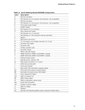
... brugte batterier bør foregå i overensstemmelse med gældende miljølovgivning. 58 Setup displays the maintenance menu again. 9. Replace the cover, plug in , the standby current from the AC power source. 11. Les piles usagées doivent être recyclées dans la mesure du possible. Select Yes... the voltage drops below . 13. Replacing the Battery A coin-cell battery (CR2032) powers the real-time clock and CMOS memory. Batterier bør om muligt genbruges. Intel Desktop Board DP55WG Product Guide 8.
... brugte batterier bør foregå i overensstemmelse med gældende miljølovgivning. 58 Setup displays the maintenance menu again. 9. Replace the cover, plug in , the standby current from the AC power source. 11. Les piles usagées doivent être recyclées dans la mesure du possible. Select Yes... the voltage drops below . 13. Replacing the Battery A coin-cell battery (CR2032) powers the real-time clock and CMOS memory. Batterier bør om muligt genbruges. Intel Desktop Board DP55WG Product Guide 8.