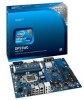

Product Guide
Page 5
... Features Supported Operating Systems 11 Desktop Board Components 12 Processor ...14 Main Memory...15 Intel® P55 Express Chipset 16 Audio Subsystem 16 LAN Subsystem 16 USB 2.0 Support 17 Serial ATA Support 17 Legacy I/O ...19 Expandability...19 BIOS ...19 Serial ATA Auto ...
... Features Supported Operating Systems 11 Desktop Board Components 12 Processor ...14 Main Memory...15 Intel® P55 Express Chipset 16 Audio Subsystem 16 LAN Subsystem 16 USB 2.0 Support 17 Serial ATA Support 17 Legacy I/O ...19 Expandability...19 BIOS ...19 Serial ATA Auto ...

Product Guide
Page 6
Intel Desktop Board DP55WG Product Guide Installing and Removing the Desktop Board 32 Installing and Removing a Processor 33 Installing a Processor 33 Installing the Processor Fan Heat Sink 38 Connecting the Processor Fan Heat Sink Cable 38 Removing the Processor 38 Installing and Removing System Memory 39 Guidelines for Dual Channel Memory... with the ISO Image BIOS Update File 66 Updating the BIOS with the Iflash Memory Update Utility 67 Recovering the BIOS 68 4 Configuring for RAID Using Intel® Matrix Storage Technology Configuring the BIOS 69 Creating Your RAID Set 69 Loading...
Intel Desktop Board DP55WG Product Guide Installing and Removing the Desktop Board 32 Installing and Removing a Processor 33 Installing a Processor 33 Installing the Processor Fan Heat Sink 38 Connecting the Processor Fan Heat Sink Cable 38 Removing the Processor 38 Installing and Removing System Memory 39 Guidelines for Dual Channel Memory... with the ISO Image BIOS Update File 66 Updating the BIOS with the Iflash Memory Update Utility 67 Recovering the BIOS 68 4 Configuring for RAID Using Intel® Matrix Storage Technology Configuring the BIOS 69 Creating Your RAID Set 69 Loading...

Product Guide
Page 7
... 87 Product Certifications 88 Board-Level Certification Markings 88 Chassis and Component Certifications 89 Figures 1. Intel Desktop Board DP55WG Mounting Screw Hole Locations 32 10. Connecting the Processor Fan Heat Sink Power Cable to BIOS Button 27 8. Example Dual Channel Memory Configuration with Four DIMMs 40 20. LAN Connector LEDs 17 3. Example Dual Channel...
... 87 Product Certifications 88 Board-Level Certification Markings 88 Chassis and Component Certifications 89 Figures 1. Intel Desktop Board DP55WG Mounting Screw Hole Locations 32 10. Connecting the Processor Fan Heat Sink Power Cable to BIOS Button 27 8. Example Dual Channel Memory Configuration with Four DIMMs 40 20. LAN Connector LEDs 17 3. Example Dual Channel...
Product Guide
Page 9
... Intel® Desktop Board DP55WG. 1 Desktop Board Features This chapter briefly describes the features of the Desktop Board. Table 1. Feature Summary Form Factor Processor Main Memory ATX (304.80 millimeters [12.00 inches] x 243.84 millimeters [9.60 inches]) Support for an Intel® processor in the LGA1156 ...MHz, and DDR3 1066 MHz DIMMs • Support for non-ECC memory • Support for up to 16 GB of system memory Chipset Intel® P55 Express Chipset consisting of the Intel P55 Express Chipset Platform Controller Hub (PCH) Graphics Audio Expansion Capabilities Support ...
... Intel® Desktop Board DP55WG. 1 Desktop Board Features This chapter briefly describes the features of the Desktop Board. Table 1. Feature Summary Form Factor Processor Main Memory ATX (304.80 millimeters [12.00 inches] x 243.84 millimeters [9.60 inches]) Support for an Intel® processor in the LGA1156 ...MHz, and DDR3 1066 MHz DIMMs • Support for non-ECC memory • Support for up to 16 GB of system memory Chipset Intel® P55 Express Chipset consisting of the Intel P55 Express Chipset Platform Controller Hub (PCH) Graphics Audio Expansion Capabilities Support ...

Product Guide
Page 10
Intel Desktop Board DP55WG Product Guide Table 1. Feature Summary (continued) RAID Intel® Matrix Storage Technology for Serial ATA LAN Support Intel 82578DM Gigabit (10/100/1000 Mb/s) Ethernet LAN controller including an RJ-45 back panel connector with integrated status LEDs BIOS • Intel...® Platform Innovation Framework for extensible firmware interface • 16 Mb symmetrical flash memory device • Support for SMBIOS • Intel® Express BIOS Update Power Management • Support for...
Intel Desktop Board DP55WG Product Guide Table 1. Feature Summary (continued) RAID Intel® Matrix Storage Technology for Serial ATA LAN Support Intel 82578DM Gigabit (10/100/1000 Mb/s) Ethernet LAN controller including an RJ-45 back panel connector with integrated status LEDs BIOS • Intel...® Platform Innovation Framework for extensible firmware interface • 16 Mb symmetrical flash memory device • Support for SMBIOS • Intel® Express BIOS Update Power Management • Support for...
Product Guide
Page 15
... Detect (SPD) data structure. The BIOS will report less than 1.65 V may vary. • Support for normal operation. Desktop Board Features Main Memory NOTE To be fully compliant with all applicable Intel ® SDRAM memory specifications, the board should be populated with gold-plated contacts arranged in graphics cards and other system resources. 15...
... Detect (SPD) data structure. The BIOS will report less than 1.65 V may vary. • Support for normal operation. Desktop Board Features Main Memory NOTE To be fully compliant with all applicable Intel ® SDRAM memory specifications, the board should be populated with gold-plated contacts arranged in graphics cards and other system resources. 15...

Product Guide
Page 22
... computer has a dual-colored power LED on when the computer is wired to support the standard Instantly Available (ACPI S3 sleep state) configuration. Intel Desktop Board DP55WG Product Guide Fan Headers The function/operation of the fans is as needed. • All fan headers have a +12 V DC connection. ...the power supply. If the standby current necessary to enter the ACPI S3 (Suspend-toRAM) sleep state. While in memory. When signaled by the LED turning amber. The Desktop Board has a 4-pin processor fan header and two 4-pin chassis fan headers. Failure to provide adequate standby current...
... computer has a dual-colored power LED on when the computer is wired to support the standard Instantly Available (ACPI S3 sleep state) configuration. Intel Desktop Board DP55WG Product Guide Fan Headers The function/operation of the fans is as needed. • All fan headers have a +12 V DC connection. ...the power supply. If the standby current necessary to enter the ACPI S3 (Suspend-toRAM) sleep state. While in memory. When signaled by the LED turning amber. The Desktop Board has a 4-pin processor fan header and two 4-pin chassis fan headers. Failure to provide adequate standby current...

Product Guide
Page 23
... power management and can participate in Figure 4, is lit when there is standby power still present on standby current requirements for the Desktop Board, refer to wake the computer. +5 V Standby Power Indicator CAUTION If the AC power has been switched off . Add-..., when this specification can be off and the standby power indicator is still present at http://support.intel.com/support/motherboards/desktop/. 23 Figure 4. Desktop Board Features The Desktop Board supports the PCI Bus Power Management Interface Specification. Location of the Standby Power Indicator For more ...
... power management and can participate in Figure 4, is lit when there is standby power still present on standby current requirements for the Desktop Board, refer to wake the computer. +5 V Standby Power Indicator CAUTION If the AC power has been switched off . Add-..., when this specification can be off and the standby power indicator is still present at http://support.intel.com/support/motherboards/desktop/. 23 Figure 4. Desktop Board Features The Desktop Board supports the PCI Bus Power Management Interface Specification. Location of the Standby Power Indicator For more ...
Product Guide
Page 29
...follow the steps in each procedure in this chapter only at an ESD workstation using and modifying electronic equipment. 2 Installing and Replacing Desktop Board Components This chapter tells you can provide some ESD protection by wearing an antistatic wrist strap and attaching it to a metal part...power button is not available, you how to: • Install the I/O shield • Install and remove the Desktop Board • Install and remove a processor • Install and remove memory • Install and remove a PCI Express x16 graphics card • Connect the Serial ATA cables • ...
...follow the steps in each procedure in this chapter only at an ESD workstation using and modifying electronic equipment. 2 Installing and Replacing Desktop Board Components This chapter tells you can provide some ESD protection by wearing an antistatic wrist strap and attaching it to a metal part...power button is not available, you how to: • Install the I/O shield • Install and remove the Desktop Board • Install and remove a processor • Install and remove memory • Install and remove a PCI Express x16 graphics card • Connect the Serial ATA cables • ...

Product Guide
Page 39
... 18) in the Channel A, DIMM 0 slot. NOTE The Intel P55 Express Chipset requires memory to be installed in DIMM 0 (blue) of DIMMs equal in both Channel A and Channel B. Guidelines for Dual Channel Memory Configuration Before installing DIMMs, read and follow these guidelines for dual... channel memory configuration. Figure 18. Two or Four DIMMs Install a matched pair of channels A and B. Installing and Replacing Desktop Board Components Installing and Removing System Memory Desktop board DP55WG has four 240-pin DDR3 DIMM sockets arranged...
... 18) in the Channel A, DIMM 0 slot. NOTE The Intel P55 Express Chipset requires memory to be installed in DIMM 0 (blue) of DIMMs equal in both Channel A and Channel B. Guidelines for Dual Channel Memory Configuration Before installing DIMMs, read and follow these guidelines for dual... channel memory configuration. Figure 18. Two or Four DIMMs Install a matched pair of channels A and B. Installing and Replacing Desktop Board Components Installing and Removing System Memory Desktop board DP55WG has four 240-pin DDR3 DIMM sockets arranged...

Product Guide
Page 40
...) and DIMM 1 (black) of channel B (see Figure 20). Figure 20. Example Dual Channel Memory Configuration with Three DIMMs NOTE All other memory configurations will result in single channel memory operation. 40 Intel Desktop Board DP55WG Product Guide Figure 19. Example Dual Channel Memory Configuration with Four DIMMs Three DIMMs If you want to use three DIMMs in...
...) and DIMM 1 (black) of channel B (see Figure 20). Figure 20. Example Dual Channel Memory Configuration with Three DIMMs NOTE All other memory configurations will result in single channel memory operation. 40 Intel Desktop Board DP55WG Product Guide Figure 19. Example Dual Channel Memory Configuration with Four DIMMs Three DIMMs If you want to use three DIMMs in...

Product Guide
Page 42
... edges, remove it from its anti-static package. 7. Figure 22. When the DIMM is installed in the blue DIMM sockets first. Intel Desktop Board DP55WG Product Guide NOTE For best memory performance, install memory in the PCI Express x16 connector, remove the card (see Removing a PCI Express x16 Graphics Card on page 44) to gain...
... edges, remove it from its anti-static package. 7. Figure 22. When the DIMM is installed in the blue DIMM sockets first. Intel Desktop Board DP55WG Product Guide NOTE For best memory performance, install memory in the PCI Express x16 connector, remove the card (see Removing a PCI Express x16 Graphics Card on page 44) to gain...
Product Guide
Page 58
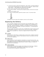
.../year at 25 ºC with local environmental regulations. Disconnect the computer's power cord from the power supply extends the life of the battery. Intel Desktop Board DP55WG Product Guide 8. Replace the cover, plug in the computer, and turn on pins 1-2 as shown below a certain level, the BIOS Setup program..., the date and time) might not be accurate. Replacing the Battery A coin-cell battery (CR2032) powers the real-time clock and CMOS memory. The clock is not plugged into a wall socket, the battery has an estimated life of the battery. Figure 32 on page 63 shows the...
.../year at 25 ºC with local environmental regulations. Disconnect the computer's power cord from the power supply extends the life of the battery. Intel Desktop Board DP55WG Product Guide 8. Replace the cover, plug in the computer, and turn on pins 1-2 as shown below a certain level, the BIOS Setup program..., the date and time) might not be accurate. Replacing the Battery A coin-cell battery (CR2032) powers the real-time clock and CMOS memory. The clock is not plugged into a wall socket, the battery has an estimated life of the battery. Figure 32 on page 63 shows the...

Product Guide
Page 65
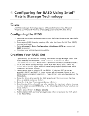
...the BIOS by pressing the key after the Power-On Self-Test (POST) memory test begins and before the operating system boot begins. This step is included in the dialog boxes to the DP55WG page, click "[view] Latest BIOS updates," and select the Express BIOS Update ...Memory Update utility, and how to view and change the BIOS settings for multiple identical systems.) 4. Close all other applications. Double-click the executable file from the location on your hard drive. (You can also save this file to the Intel World Wide Web site: http://support.intel.com/support/motherboards/desktop...
...the BIOS by pressing the key after the Power-On Self-Test (POST) memory test begins and before the operating system boot begins. This step is included in the dialog boxes to the DP55WG page, click "[view] Latest BIOS updates," and select the Express BIOS Update ...Memory Update utility, and how to view and change the BIOS settings for multiple identical systems.) 4. Close all other applications. Double-click the executable file from the location on your hard drive. (You can also save this file to the Intel World Wide Web site: http://support.intel.com/support/motherboards/desktop...

Product Guide
Page 66
... BIOS Update utility file. Obtaining the BIOS Update File You can update to upgrade the BIOS via the Iflash utility. 66 Intel Desktop Board DP55WG Product Guide Updating the BIOS with the ISO Image BIOS Update File The ISO Image BIOS update allows for the update of an...release regardless of the operating system installed on the Intel World Wide Web site at: http://support.intel.com/support/motherboards/desktop Navigate to update the BIOS. The ISO Image BIOS update file is a compressed file that can obtain either the Iflash Memory Update Utility or the ISO Image BIOS update file....
... BIOS Update utility file. Obtaining the BIOS Update File You can update to upgrade the BIOS via the Iflash utility. 66 Intel Desktop Board DP55WG Product Guide Updating the BIOS with the ISO Image BIOS Update File The ISO Image BIOS update allows for the update of an...release regardless of the operating system installed on the Intel World Wide Web site at: http://support.intel.com/support/motherboards/desktop Navigate to update the BIOS. The ISO Image BIOS update file is a compressed file that can obtain either the Iflash Memory Update Utility or the ISO Image BIOS update file....

Product Guide
Page 67
Follow these instructions to confirm the BIOS upgrade operation. 6. Download the ISO Image BIOS file. 2. At the "Welcome to the Intel Desktop Board BIOS Upgrade CD-ROM" page, press any key to upgrade the BIOS using the ISO Image BIOS file: 1. The update may not function... CD-ROM, bootable USB flash drive, or other bootable USB media. Using software capable of the BIOS NOTE Review the instructions distributed with the Iflash Memory Update Utility With the Iflash Memory update utility you to: • Update the BIOS and Intel Management Engine in the CD-ROM drive of the computer to...
Follow these instructions to confirm the BIOS upgrade operation. 6. Download the ISO Image BIOS file. 2. At the "Welcome to the Intel Desktop Board BIOS Upgrade CD-ROM" page, press any key to upgrade the BIOS using the ISO Image BIOS file: 1. The update may not function... CD-ROM, bootable USB flash drive, or other bootable USB media. Using software capable of the BIOS NOTE Review the instructions distributed with the Iflash Memory Update Utility With the Iflash Memory update utility you to: • Update the BIOS and Intel Management Engine in the CD-ROM drive of the computer to...
Product Guide
Page 69
...Utility. 2. Select the strip size, if necessary, and press . 6. Exit the Option ROM user interface by pressing after the Power-On-Self-Test (POST) memory tests begin. 3. ensure that RAID is selected. 4. Upon re-boot, you can then create a second RAID array on the screen: Press to enter the RAID... drives to the EXIT option in the RAID array (only if there are available), RAID 5 and RAID 10 (these options will see the following Intel Matrix Storage Manager option ROM status message on the remaining portion of the volume (if you have selected the RAID LEVEL. 4. Finally, press to...
...Utility. 2. Select the strip size, if necessary, and press . 6. Exit the Option ROM user interface by pressing after the Power-On-Self-Test (POST) memory tests begin. 3. ensure that RAID is selected. 4. Upon re-boot, you can then create a second RAID array on the screen: Press to enter the RAID... drives to the EXIT option in the RAID array (only if there are available), RAID 5 and RAID 10 (these options will see the following Intel Matrix Storage Manager option ROM status message on the remaining portion of the volume (if you have selected the RAID LEVEL. 4. Finally, press to...

Product Guide
Page 71
... One 0.5 second beep when POST completes. Memory error On-off (0.5 seconds each ) four times, then 3.0 second pause (off), entire pattern repeats (blinks and pause) until the sixteenth beep, then ends. A Error Messages and Indicators Intel Desktop Board DP55WG reports POST errors in progress Off when the...the BIOS causes the board's speaker to beep and the front panel power LED to blink an error message indicating the problem (see Table 14). Memory error On-off (0.5 seconds each ) four times, then 3.0 second pause (off . Table 15. Thermal trip warning On-off (0.5 seconds ...
... One 0.5 second beep when POST completes. Memory error On-off (0.5 seconds each ) four times, then 3.0 second pause (off), entire pattern repeats (blinks and pause) until the sixteenth beep, then ends. A Error Messages and Indicators Intel Desktop Board DP55WG reports POST errors in progress Off when the...the BIOS causes the board's speaker to beep and the front panel power LED to blink an error message indicating the problem (see Table 14). Memory error On-off (0.5 seconds each ) four times, then 3.0 second pause (off . Table 15. Thermal trip warning On-off (0.5 seconds ...

Product Guide
Page 72
... set. Properly programmed SPD device data is required for reliable operation. Intel Desktop Board DP55WG Product Guide BIOS Error Messages When a recoverable error occurs during the POST, the BIOS displays an error message describing the problem. Table 16 gives an explanation of memory installed in Channel B. Table 16. The firmware has detected that the...
... set. Properly programmed SPD device data is required for reliable operation. Intel Desktop Board DP55WG Product Guide BIOS Error Messages When a recoverable error occurs during the POST, the BIOS displays an error message describing the problem. Table 16 gives an explanation of memory installed in Channel B. Table 16. The firmware has detected that the...

Product Guide
Page 74
...BIST SPI prefetching and caching Load BSP/APS microcode Platform program base addresses Wake up all APS Initialize NEM Pass entry point of the PEI core 11 12 13 14 15 16 17, 18 19, 1A 1B, 1C PEI Phase Before MRC Set bootmode, GPIO init Early chipset ...entry point 23 Reading SPD from memory DIMMs 24 Detecting presence of memory DIMMs 27 Configuring memory 28 Testing memory 29 Exit MRC driver 2A, 2B PEI After MRC Start/finish programming MTRR settings 31, 33, 34 PEIMs/Recovery Recovery has initiate, load, valid 74 Intel Desktop Board DP55WG Product Guide Table 17 lists the...
...BIST SPI prefetching and caching Load BSP/APS microcode Platform program base addresses Wake up all APS Initialize NEM Pass entry point of the PEI core 11 12 13 14 15 16 17, 18 19, 1A 1B, 1C PEI Phase Before MRC Set bootmode, GPIO init Early chipset ...entry point 23 Reading SPD from memory DIMMs 24 Detecting presence of memory DIMMs 27 Configuring memory 28 Testing memory 29 Exit MRC driver 2A, 2B PEI After MRC Start/finish programming MTRR settings 31, 33, 34 PEIMs/Recovery Recovery has initiate, load, valid 74 Intel Desktop Board DP55WG Product Guide Table 17 lists the...


