
Product Guide
Page 5
... Operating Systems 11 Desktop Board Components 12 Processor ...14 Main Memory...15 Intel® P55 Express Chipset 16 ...Audio Subsystem 16 LAN Subsystem 16 USB 2.0 Support 17 Serial ATA Support 17 Legacy I/O ...19 Expandability...19 BIOS ...19 Serial ATA Auto Configuration 19 PCI Express* Auto Configuration 19 Security Passwords 20 Hardware Management 20 Hardware Monitoring and Fan Speed Control 20 Intel......28 Real-Time Clock 28 2 Installing and Replacing Desktop Board Components Before You Begin 29 Installation Precautions 30 Prevent Power Supply ...
... Operating Systems 11 Desktop Board Components 12 Processor ...14 Main Memory...15 Intel® P55 Express Chipset 16 ...Audio Subsystem 16 LAN Subsystem 16 USB 2.0 Support 17 Serial ATA Support 17 Legacy I/O ...19 Expandability...19 BIOS ...19 Serial ATA Auto Configuration 19 PCI Express* Auto Configuration 19 Security Passwords 20 Hardware Management 20 Hardware Monitoring and Fan Speed Control 20 Intel......28 Real-Time Clock 28 2 Installing and Replacing Desktop Board Components Before You Begin 29 Installation Precautions 30 Prevent Power Supply ...

Product Guide
Page 7
...Electromagnetic Compatibility (EMC) Compliance 87 Product Certifications 88 Board-Level Certification Markings 88 Chassis and Component Certifications 89 Figures 1. Intel Desktop Board DP55WG Mounting Screw Hole Locations 32 10. Secure the Load Plate in Place 37 17. Removing a PCI Express x16 Graphics ... DP55WG Components 12 2. Onboard Power Button 25 6. Remove the Processor from the Protective Cover 36 14. Installing a DIMM 42 23. LAN Connector LEDs 17 3. Installing the I/O Shield 31 9. Installing a PCI Express x16 Graphics Card 44 24. Location of the Processor and ...
...Electromagnetic Compatibility (EMC) Compliance 87 Product Certifications 88 Board-Level Certification Markings 88 Chassis and Component Certifications 89 Figures 1. Intel Desktop Board DP55WG Mounting Screw Hole Locations 32 10. Secure the Load Plate in Place 37 17. Removing a PCI Express x16 Graphics ... DP55WG Components 12 2. Onboard Power Button 25 6. Remove the Processor from the Protective Cover 36 14. Installing a DIMM 42 23. LAN Connector LEDs 17 3. Installing the I/O Shield 31 9. Installing a PCI Express x16 Graphics Card 44 24. Location of the Processor and ...
Product Guide
Page 29
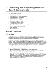
... Components This chapter tells you how to: • Install the I/O shield • Install and remove the Desktop Board • Install and remove a processor • Install and remove memory • Install and remove a PCI Express x16 graphics card • Connect the Serial ATA ...
... Components This chapter tells you how to: • Install the I/O shield • Install and remove the Desktop Board • Install and remove a processor • Install and remove memory • Install and remove a PCI Express x16 graphics card • Connect the Serial ATA ...

Product Guide
Page 31
Figure 8. Installing the I /O shield. Installing and Replacing Desktop Board Components Installing the I/O Shield The Desktop Board comes with an I /O Shield 31 Install the I/O shield before installing the Desktop Board in Figure 8. If the shield does not fit, obtain a properly sized shield from dust and foreign objects, and promotes correct airflow within the chassis. Press the shield into place so that it...
Figure 8. Installing the I /O shield. Installing and Replacing Desktop Board Components Installing the I/O Shield The Desktop Board comes with an I /O Shield 31 Install the I/O shield before installing the Desktop Board in Figure 8. If the shield does not fit, obtain a properly sized shield from dust and foreign objects, and promotes correct airflow within the chassis. Press the shield into place so that it...

Product Guide
Page 51
... two USB devices. Pins 1 and 3 of the front panel header. Table 9 shows the pin assignments for each USB 2.0 header. Table 10. Use a shielded cable that have an unshielded cable attached to a USB port might not meet FCC Class B requirements, even if no device or a low-speed USB device... is attached to this header duplicate the signals on pins 2 and 4 of this header. Installing and Replacing Desktop Board Components Alternate Front Panel Power LED Header Figure 27, F shows the location of the USB 2.0 headers. If your chassis has a three-pin ...
... two USB devices. Pins 1 and 3 of the front panel header. Table 9 shows the pin assignments for each USB 2.0 header. Table 10. Use a shielded cable that have an unshielded cable attached to a USB port might not meet FCC Class B requirements, even if no device or a low-speed USB device... is attached to this header duplicate the signals on pins 2 and 4 of this header. Installing and Replacing Desktop Board Components Alternate Front Panel Power LED Header Figure 27, F shows the location of the USB 2.0 headers. If your chassis has a three-pin ...

Product Guide
Page 87
... following when reading the installation instructions for the host chassis, power supply, and other modules: • Product certifications or lack of certifications • External I/O cable shielding and filtering • Mounting, grounding, and bonding requirements • Keying connectors when mating the wrong connectors could be required on a representative sample of the newly...
... following when reading the installation instructions for the host chassis, power supply, and other modules: • Product certifications or lack of certifications • External I/O cable shielding and filtering • Mounting, grounding, and bonding requirements • Keying connectors when mating the wrong connectors could be required on a representative sample of the newly...