Product Specification
Page 5
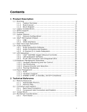
Contents 1 Product Description 1.1 Overview 9 1.1.1 Feature Summary 9 1.1.2 Board Layout 11 1.1.3 Block Diagram 13 1.2 Legacy Considerations 13 1.3 Online Support 14 1.4 Processor 14 1.5 System Memory 15 1.5.1 Memory Configurations 16 1.6 Intel® P55 Express Chipset 18 1.6.1 USB 18 1.6.2 SATA Interfaces 19 1.7 Real-Time Clock Subsystem 20 1.8 Audio Subsystem 20 1.8.1 Audio Subsystem Software 21 1.8.2 Audio Connectors and Headers 21 1.8.3 6-...
Contents 1 Product Description 1.1 Overview 9 1.1.1 Feature Summary 9 1.1.2 Board Layout 11 1.1.3 Block Diagram 13 1.2 Legacy Considerations 13 1.3 Online Support 14 1.4 Processor 14 1.5 System Memory 15 1.5.1 Memory Configurations 16 1.6 Intel® P55 Express Chipset 18 1.6.1 USB 18 1.6.2 SATA Interfaces 19 1.7 Real-Time Clock Subsystem 20 1.8 Audio Subsystem 20 1.8.1 Audio Subsystem Software 21 1.8.2 Audio Connectors and Headers 21 1.8.3 6-...
Product Specification
Page 6
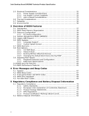
Intel Desktop Board DP55WB Technical Product Specification 2.5 Electrical Considerations 52 2.5.1 Power Supply Considerations 52 2.5.2 Fan Header Current Capability 53 2.5.3 Add-in Board Considerations 53 2.6 Thermal Considerations 53 2.7 Reliability 56 2.8 Environmental 56 3 Overview of BIOS Features 3.1 Introduction 57 3.2 BIOS Flash Memory Organization 58 3.3 Resource Configuration 58 3.3.1 PCI Autoconfiguration 58 3.4 System Management BIOS (SMBIOS 59 3.5 Legacy USB...
Intel Desktop Board DP55WB Technical Product Specification 2.5 Electrical Considerations 52 2.5.1 Power Supply Considerations 52 2.5.2 Fan Header Current Capability 53 2.5.3 Add-in Board Considerations 53 2.6 Thermal Considerations 53 2.7 Reliability 56 2.8 Environmental 56 3 Overview of BIOS Features 3.1 Introduction 57 3.2 BIOS Flash Memory Organization 58 3.3 Resource Configuration 58 3.3.1 PCI Autoconfiguration 58 3.4 System Management BIOS (SMBIOS 59 3.5 Legacy USB...
Product Specification
Page 7
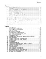
...Connector LED States 23 6. S/PDIF Header 42 16. Main Power Connector 44 20. States for Intel HD Audio 41 13. Recommended Power Supply Current Values 52 25. Effects of the Jumper Block...Audio Header for a Two-Color Power LED 46 23. Chassis Intrusion Header 42 17. Processor Core Power Connector 43 19. States for AC '97 Audio 41 14. Power States and Targeted System...Shown in Figure 10 40 11. Contents Figures 1 Major Board Components 11 2 Block Diagram 13 3 Memory Channel and DIMM Configuration 17 4 Back Panel Audio Connectors 21 5 LAN Connector LED Locations 23 6 Thermal...
...Connector LED States 23 6. S/PDIF Header 42 16. Main Power Connector 44 20. States for Intel HD Audio 41 13. Recommended Power Supply Current Values 52 25. Effects of the Jumper Block...Audio Header for a Two-Color Power LED 46 23. Chassis Intrusion Header 42 17. Processor Core Power Connector 43 19. States for AC '97 Audio 41 14. Power States and Targeted System...Shown in Figure 10 40 11. Contents Figures 1 Major Board Components 11 2 Block Diagram 13 3 Memory Channel and DIMM Configuration 17 4 Back Panel Audio Connectors 21 5 LAN Connector LED Locations 23 6 Thermal...
Product Specification
Page 9
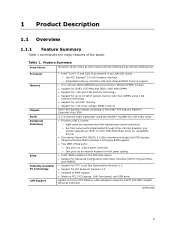
...Intel® Core™ i7 and Core i5 processors in the SPI Flash device • Support for Advanced Configuration and Power Interface (ACPI), Plug and Play, and SMBIOS • Support for PCI* Local Bus Specification Revision 2.2 • Support for 1.35 V low voltage JEDEC memory Intel® P55 Express Chipset consisting of the Intel® P55... • Intel® BIOS resident in an LGA1156 socket ― One PCI Express* 2.0 x16 Graphics interface ― Integrated memory controller with dual channel DDR3 memory support • Four 240-pin DDR3 SDRAM Dual Inline Memory Module (DIMM...
...Intel® Core™ i7 and Core i5 processors in the SPI Flash device • Support for Advanced Configuration and Power Interface (ACPI), Plug and Play, and SMBIOS • Support for PCI* Local Bus Specification Revision 2.2 • Support for 1.35 V low voltage JEDEC memory Intel® P55 Express Chipset consisting of the Intel® P55... • Intel® BIOS resident in an LGA1156 socket ― One PCI Express* 2.0 x16 Graphics interface ― Integrated memory controller with dual channel DDR3 memory support • Four 240-pin DDR3 SDRAM Dual Inline Memory Module (DIMM...
Product Specification
Page 14
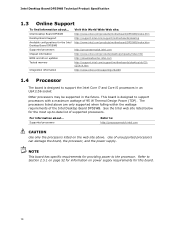
...Intel Desktop Board DP55WB Supported processors Chipset information BIOS and driver updates Tested memory Integration information Visit this board. 14 Use of the Intel Desktop Board DP55WB. The processors listed above . See the Intel web site listed below for this World Wide Web site: http://www.intel.com/products/motherboard/DP55WB/index.htm http://support.intel.com/support/motherboards/desktop http://www.intel.com/products/motherboard/DP55WB...Refer to support the Intel Core i7 and Core i5 processors in an LGA1156 socket Other processors may be supported in the future.
...Intel Desktop Board DP55WB Supported processors Chipset information BIOS and driver updates Tested memory Integration information Visit this board. 14 Use of the Intel Desktop Board DP55WB. The processors listed above . See the Intel web site listed below for this World Wide Web site: http://www.intel.com/products/motherboard/DP55WB/index.htm http://support.intel.com/support/motherboards/desktop http://www.intel.com/products/motherboard/DP55WB...Refer to support the Intel Core i7 and Core i5 processors in an LGA1156 socket Other processors may be supported in the future.
Product Specification
Page 15
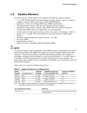
... may not function under the determined frequency. If non-SPD memory is installed, the BIOS will attempt to : http://support.intel.com/support/motherboards/desktop/sb/ CS-025414.htm 15 Table 3 lists the supported DIMM configurations. For information about... Tested Memory Refer to correctly configure the memory settings, but performance and reliability may be populated with...
... may not function under the determined frequency. If non-SPD memory is installed, the BIOS will attempt to : http://support.intel.com/support/motherboards/desktop/sb/ CS-025414.htm 15 Table 3 lists the supported DIMM configurations. For information about... Tested Memory Refer to correctly configure the memory settings, but performance and reliability may be populated with...
Product Specification
Page 16
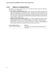
...If different speed DIMMs are used between channels, the slowest memory timing will be equal. Technology and device width can vary from one channel to : http://www.intel.com/support/motherboards/desktop/sb/cs011965.htm 16 This mode is used . If...when only a single DIMM is enabled when the installed memory capacities of memory organization: • Dual channel (Interleaved) mode. Intel Desktop Board DP55WB Technical Product Specification 1.5.1 Memory Configurations The Intel Core i7 and Core i5 processors in the LGA1156 socket support the following types of both DIMM channels are...
...If different speed DIMMs are used between channels, the slowest memory timing will be equal. Technology and device width can vary from one channel to : http://www.intel.com/support/motherboards/desktop/sb/cs011965.htm 16 This mode is used . If...when only a single DIMM is enabled when the installed memory capacities of memory organization: • Dual channel (Interleaved) mode. Intel Desktop Board DP55WB Technical Product Specification 1.5.1 Memory Configurations The Intel Core i7 and Core i5 processors in the LGA1156 socket support the following types of both DIMM channels are...
Product Specification
Page 17
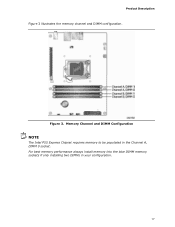
For best memory performance always install memory into the blue DIMM memory sockets if only installing two DIMMs in the Channel A, DIMM 0 socket. Memory Channel and DIMM Configuration NOTE The Intel P55 Express Chipset requires memory to be populated in your configuration. 17 Figure 3. Product Description Figure 3 illustrates the memory channel and DIMM configuration.
For best memory performance always install memory into the blue DIMM memory sockets if only installing two DIMMs in the Channel A, DIMM 0 socket. Memory Channel and DIMM Configuration NOTE The Intel P55 Express Chipset requires memory to be populated in your configuration. 17 Figure 3. Product Description Figure 3 illustrates the memory channel and DIMM configuration.
Product Specification
Page 20
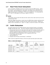
Intel Desktop Board DP55WB Technical Product Specification 1.7 Real-Time Clock Subsystem A coin-cell battery (CR2032) powers the real-time clock and CMOS memory. NOTE If the battery and AC power fail date and time values will be reset and the user will be accurate. Figure 1 on...BIOS Setup program settings stored in , the standby current from the power supply extends the life of the battery. 1.8 Audio Subsystem The board supports the Intel High Definition Audio subsystem based on the recognized device type. • 3-port analog audio out stack • Internal S/PDIF out • Windows ...
Intel Desktop Board DP55WB Technical Product Specification 1.7 Real-Time Clock Subsystem A coin-cell battery (CR2032) powers the real-time clock and CMOS memory. NOTE If the battery and AC power fail date and time values will be reset and the user will be accurate. Figure 1 on...BIOS Setup program settings stored in , the standby current from the power supply extends the life of the battery. 1.8 Audio Subsystem The board supports the Intel High Definition Audio subsystem based on the recognized device type. • 3-port analog audio out stack • Internal S/PDIF out • Windows ...
Product Specification
Page 35
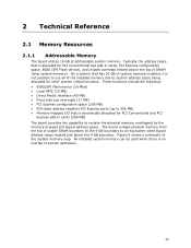
... the top of DRAM (total system memory). These functions include the following: • BIOS/SPI Flash device (16 Mbit) • Local APIC (19 MB) • Direct Media Interface (40 MB) • Front side bus interrupts (17 MB) • PCI Express configuration space (256 MB) • PCH base ...address registers PCI Express ports (up to 256 MB) • Memory-mapped I/O that is allocated for PCI Conventional bus add-in...
... the top of DRAM (total system memory). These functions include the following: • BIOS/SPI Flash device (16 Mbit) • Local APIC (19 MB) • Direct Media Interface (40 MB) • Front side bus interrupts (17 MB) • PCI Express configuration space (256 MB) • PCH base ...address registers PCI Express ports (up to 256 MB) • Memory-mapped I/O that is allocated for PCI Conventional bus add-in...
Product Specification
Page 37
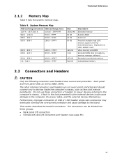
... headers are not overcurrent protected and should connect only to the PCI Conventional bus). Technical Reference 2.1.2 Memory Map Table 9 lists the system memory map. Video memory and BIOS Extended BIOS data (movable by the external devices could cause damage to the computer, the...into these connectors or headers to power devices external to the board. Dependent on video adapter used. This section describes the board's connectors. System Memory Map Address Range (decimal) Address Range (hex) 1024 K - 16777216 K 100000 - 3FFFFFFFF 960 K - 1024 K F0000 - Furthermore, ...
... headers are not overcurrent protected and should connect only to the PCI Conventional bus). Technical Reference 2.1.2 Memory Map Table 9 lists the system memory map. Video memory and BIOS Extended BIOS data (movable by the external devices could cause damage to the computer, the...into these connectors or headers to power devices external to the board. Dependent on video adapter used. This section describes the board's connectors. System Memory Map Address Range (decimal) Address Range (hex) 1024 K - 16777216 K 100000 - 3FFFFFFFF 960 K - 1024 K F0000 - Furthermore, ...
Product Specification
Page 57
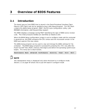
The BIOS displays a message during POST identifying the type of BIOS Features 3.1 Introduction The board uses an Intel BIOS that is in configure mode. The initial production BIOSs are identified as WBIBX10J.86A. The BIOS Setup program is powered-up, the BIOS compares ... BIOS Setup configuration jumper is set to configure mode and the computer is accessed by pressing the key after the Power-On Self-Test (POST) memory test begins and before the operating system boot begins. Maintenance Main Advanced Performance Security Power Boot Exit NOTE The maintenance menu is displayed only when...
The BIOS displays a message during POST identifying the type of BIOS Features 3.1 Introduction The board uses an Intel BIOS that is in configure mode. The initial production BIOSs are identified as WBIBX10J.86A. The BIOS Setup program is powered-up, the BIOS compares ... BIOS Setup configuration jumper is set to configure mode and the computer is accessed by pressing the key after the Power-On Self-Test (POST) memory test begins and before the operating system boot begins. Maintenance Main Advanced Performance Security Power Boot Exit NOTE The maintenance menu is displayed only when...
Product Specification
Page 58
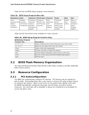
... system after adding a PCI card, the BIOS automatically configures interrupts, the I/O space, and other system resources. Intel Desktop Board DP55WB Technical Product Specification Table 28 lists the BIOS Setup program menu features. Table 29. Any interrupts set to Available ... Main Advanced Performance Security Clears passwords and displays processor information Displays processor and memory configuration Configures advanced features available through the chipset Configures Memory, Bus and Processor overrides Sets passwords and security features Power Configures power management...
... system after adding a PCI card, the BIOS automatically configures interrupts, the I/O space, and other system resources. Intel Desktop Board DP55WB Technical Product Specification Table 28 lists the BIOS Setup program menu features. Table 29. Any interrupts set to Available ... Main Advanced Performance Security Clears passwords and displays processor information Displays processor and memory configuration Configures advanced features available through the chipset Configures Memory, Bus and Processor overrides Sets passwords and security features Power Configures power management...
Product Specification
Page 59
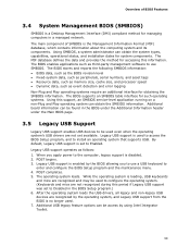
...data, such as peripherals, serial numbers, and asset tags • Resource data, such as memory size, cache size, and processor speed • Dynamic data, such as third-party management software... SMBIOS table interface for such operating systems. Using this information. Legacy USB support is a Desktop Management Interface (DMI) compliant method for accessing this support, an SMBIOS service-level application running...Legacy USB Support Legacy USB support enables USB devices to be access by using Intel Integrator Toolkit. 59 The BIOS enables applications such as event detection and error ...
...data, such as peripherals, serial numbers, and asset tags • Resource data, such as memory size, cache size, and processor speed • Dynamic data, such as third-party management software... SMBIOS table interface for such operating systems. Using this information. Legacy USB support is a Desktop Management Interface (DMI) compliant method for accessing this support, an SMBIOS service-level application running...Legacy USB Support Legacy USB support enables USB devices to be access by using Intel Integrator Toolkit. 59 The BIOS enables applications such as event detection and error ...
Product Specification
Page 60
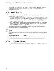
...or a CD-ROM, or from the file location on the Web. • Intel® Flash Memory Update Utility, which requires booting from a file on the Intel World Wide Web site: • Intel® Express BIOS Update utility, which enables automated updating while in US English and...the upgrade utility before attempting a BIOS update. Intel Desktop Board DP55WB Technical Product Specification To install an operating system that supports USB, verify that the updated BIOS matches the target system to http://support.intel.com/support/motherboards/desktop/sb /CS-022312.htm. 3.6.1 Language Support The...
...or a CD-ROM, or from the file location on the Web. • Intel® Flash Memory Update Utility, which requires booting from a file on the Intel World Wide Web site: • Intel® Express BIOS Update utility, which enables automated updating while in US English and...the upgrade utility before attempting a BIOS update. Intel Desktop Board DP55WB Technical Product Specification To install an operating system that supports USB, verify that the updated BIOS matches the target system to http://support.intel.com/support/motherboards/desktop/sb /CS-022312.htm. 3.6.1 Language Support The...
Product Specification
Page 65
Overview of BIOS Features 3.11 BIOS Performance Features The BIOS includes the following options to provide custom performance enhancements when using Intel Core i7 and Intel Core i5 processors in an LGA1156 socket. • Host Clock frequency adjustment • Processor multiplier adjustment (processor multiplier can only be adjusted down) • Processor voltage adjustment • Memory multiplier adjustment • Memory voltage adjustment • Uncore voltage adjustment 65
Overview of BIOS Features 3.11 BIOS Performance Features The BIOS includes the following options to provide custom performance enhancements when using Intel Core i7 and Intel Core i5 processors in an LGA1156 socket. • Host Clock frequency adjustment • Processor multiplier adjustment (processor multiplier can only be adjusted down) • Processor voltage adjustment • Memory multiplier adjustment • Memory voltage adjustment • Uncore voltage adjustment 65
Product Specification
Page 67
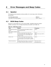
... powered off ), entire pattern repeats (beeps and pause) once and the BIOS will continue to beep an error message describing the problem (see Table 33). Memory error On-off (1.0 second each) three times, then 2.5-second pause (off (1.0 second each ) for 8 beeps, followed by system shut down. For information about The location...
... powered off ), entire pattern repeats (beeps and pause) once and the BIOS will continue to beep an error message describing the problem (see Table 33). Memory error On-off (1.0 second each) three times, then 2.5-second pause (off (1.0 second each ) for 8 beeps, followed by system shut down. For information about The location...
Product Specification
Page 68
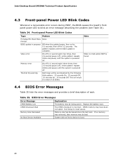
... On-off (1.0 second each . Note When no memory was removed, then memory may be bad. Memory Size Decreased Memory size has decreased since the last boot. Intel Desktop Board DP55WB Technical Product Specification 4.3 Front-panel Power LED Blink Codes Whenever a recoverable error occurs during POST, the BIOS causes the ... 34). Thermal trip warning Each beep will result in progress Off when the update begins, then on for 0.5 seconds, then off . CMOS memory may be accompanied by the following blink pattern: .25 seconds On, .25 seconds Off, .25 seconds On, .25 seconds Off. Front-...
... On-off (1.0 second each . Note When no memory was removed, then memory may be bad. Memory Size Decreased Memory size has decreased since the last boot. Intel Desktop Board DP55WB Technical Product Specification 4.3 Front-panel Power LED Blink Codes Whenever a recoverable error occurs during POST, the BIOS causes the ... 34). Thermal trip warning Each beep will result in progress Off when the update begins, then on for 0.5 seconds, then off . CMOS memory may be accompanied by the following blink pattern: .25 seconds On, .25 seconds Off, .25 seconds On, .25 seconds Off. Front-...
Product Specification
Page 69
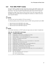
...codes requires a PCI bus add-in hexadecimal. Table 36. CF Reserved for new busses). BF Boot Devices: Includes fixed media and removable media. A0 - EE: Miscellaneous codes. The following tables provide information about the POST codes generated by any PEIM/driver for ...debug. 10 - 1F Host Processors: 1F is an unrecoverable CPU error. 20 - 2F Memory/Chipset: 2F is an unrecoverable error. 80 ...
...codes requires a PCI bus add-in hexadecimal. Table 36. CF Reserved for new busses). BF Boot Devices: Includes fixed media and removable media. A0 - EE: Miscellaneous codes. The following tables provide information about the POST codes generated by any PEIM/driver for ...debug. 10 - 1F Host Processors: 1F is an unrecoverable CPU error. 20 - 2F Memory/Chipset: 2F is an unrecoverable error. 80 ...
Product Specification
Page 70
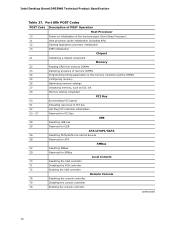
...initialization Chipset 21 Initializing a chipset component Memory 22 Reading SPD from memory DIMMs 23 Detecting presence of memory DIMMs 24 Programming timing parameters in the memory controller and the DIMMs 25 Configuring memory 26 Optimizing memory settings 27 Initializing memory, such as ECC init 29 Memory testing completed PCI Bus 50 Enumerating ...controller Remote Console 78 Resetting the console controller 79 Disabling the console controller 7A Enabling the console controller continued 70 Intel Desktop Board DP55WB Technical Product Specification Table 37.
...initialization Chipset 21 Initializing a chipset component Memory 22 Reading SPD from memory DIMMs 23 Detecting presence of memory DIMMs 24 Programming timing parameters in the memory controller and the DIMMs 25 Configuring memory 26 Optimizing memory settings 27 Initializing memory, such as ECC init 29 Memory testing completed PCI Bus 50 Enumerating ...controller Remote Console 78 Resetting the console controller 79 Disabling the console controller 7A Enabling the console controller continued 70 Intel Desktop Board DP55WB Technical Product Specification Table 37.


