Product Specification
Page 5
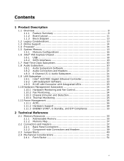
Contents 1 Product Description 1.1 Overview 9 1.1.1 Feature Summary 9 1.1.2 Board Layout 11 1.1.3 Block Diagram 13 1.2 Legacy Considerations 13 1.3 Online Support 14 1.4 Processor 14 1.5 System Memory 15 1.5.1 Memory Configurations 16 1.6 Intel® P55 Express Chipset 18 1.6.1 USB 18 1.6.2 SATA Interfaces 19 1.7 Real-Time Clock Subsystem 20 1.8 Audio Subsystem 20 1.8.1 Audio Subsystem Software 21 1.8.2 Audio Connectors and Headers 21 1.8.3 6-...
Contents 1 Product Description 1.1 Overview 9 1.1.1 Feature Summary 9 1.1.2 Board Layout 11 1.1.3 Block Diagram 13 1.2 Legacy Considerations 13 1.3 Online Support 14 1.4 Processor 14 1.5 System Memory 15 1.5.1 Memory Configurations 16 1.6 Intel® P55 Express Chipset 18 1.6.1 USB 18 1.6.2 SATA Interfaces 19 1.7 Real-Time Clock Subsystem 20 1.8 Audio Subsystem 20 1.8.1 Audio Subsystem Software 21 1.8.2 Audio Connectors and Headers 21 1.8.3 6-...
Product Specification
Page 7
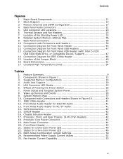
...and Rear Chassis (4-Pin) Fan Headers 42 18. Processor Core Power Connector 43 19. BIOS Setup Configuration Jumper Settings 50 24. Recommended Power Supply Current Values 52 25. LAN Connector LED States 23 6. Main Power Connector 44 20. Supported Memory Configurations 15 4. Effects of the Jumper Block ...12 Connection Diagram for Front Panel USB Headers 47 13 Connection Diagram for Front Panel USB Header (with Intel Z-U130 USB Solid-State Drive, or Compatible Device, Support 47 14 Connection Diagram for IEEE 1394a Header 48 15 Location of Pressing the Power Switch 26 7. ...
...and Rear Chassis (4-Pin) Fan Headers 42 18. Processor Core Power Connector 43 19. BIOS Setup Configuration Jumper Settings 50 24. Recommended Power Supply Current Values 52 25. LAN Connector LED States 23 6. Main Power Connector 44 20. Supported Memory Configurations 15 4. Effects of the Jumper Block ...12 Connection Diagram for Front Panel USB Headers 47 13 Connection Diagram for Front Panel USB Header (with Intel Z-U130 USB Solid-State Drive, or Compatible Device, Support 47 14 Connection Diagram for IEEE 1394a Header 48 15 Location of Pressing the Power Switch 26 7. ...
Product Specification
Page 9
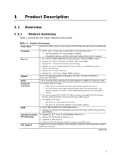
...interfaces through Intel P55 Express Chipset with Intel Matrix Storage Technology RAID support • Two IEEE 1394a ports: ― One port via a back panel connector ― One port via an internal header for front panel cabling • Intel® BIOS resident in an LGA1156 socket ...inches [243.84 millimeters by 243.84 millimeters]) Processor Memory Chipset Audio Peripheral Interfaces BIOS Instantly Available PC Technology LAN Support • Intel® Core™ i7 and Core i5 processors in the SPI Flash device • Support for Advanced Configuration and Power Interface (ACPI), ...
...interfaces through Intel P55 Express Chipset with Intel Matrix Storage Technology RAID support • Two IEEE 1394a ports: ― One port via a back panel connector ― One port via an internal header for front panel cabling • Intel® BIOS resident in an LGA1156 socket ...inches [243.84 millimeters by 243.84 millimeters]) Processor Memory Chipset Audio Peripheral Interfaces BIOS Instantly Available PC Technology LAN Support • Intel® Core™ i7 and Core i5 processors in the SPI Flash device • Support for Advanced Configuration and Power Interface (ACPI), ...
Product Specification
Page 10
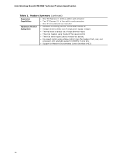
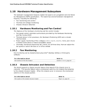
... speed control • Three fan sense inputs used to monitor fan activity • Fan speed control using voltage control (4-pin fan headers front, rear, and processor) with selectable support in BIOS for 3 wire fans • Support for Platform Environmental Control Interface (PECI) 10 Intel Desktop Board DP55WB Technical Product Specification Table 1.
... speed control • Three fan sense inputs used to monitor fan activity • Fan speed control using voltage control (4-pin fan headers front, rear, and processor) with selectable support in BIOS for 3 wire fans • Support for Platform Environmental Control Interface (PECI) 10 Intel Desktop Board DP55WB Technical Product Specification Table 1.
Product Specification
Page 14
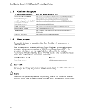
...://support.intel.com/support/motherboards/desktop http://www.intel.com/products/motherboard/DP55WB/index.htm http://processormatch.intel.com http://www.intel.com/products/desktop/chipsets/index.htm http://downloadcenter.intel.com http://support.intel.com/support/motherboards/desktop/sb/CS025414.htm http://www.intel.com/support/go/buildit 1.4 Processor The board is designed to support processors with a maximum wattage of supported processors. The processors listed above . Supported processors Refer to support the Intel Core i7 and Core i5 processors in an LGA1156 socket Other processors...
...://support.intel.com/support/motherboards/desktop http://www.intel.com/products/motherboard/DP55WB/index.htm http://processormatch.intel.com http://www.intel.com/products/desktop/chipsets/index.htm http://downloadcenter.intel.com http://support.intel.com/support/motherboards/desktop/sb/CS025414.htm http://www.intel.com/support/go/buildit 1.4 Processor The board is designed to support processors with a maximum wattage of supported processors. The processors listed above . Supported processors Refer to support the Intel Core i7 and Core i5 processors in an LGA1156 socket Other processors...
Product Specification
Page 16
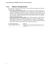
.... For information about... If different speed DIMMs are used when only a single DIMM is equivalent to : http://www.intel.com/support/motherboards/desktop/sb/cs011965.htm 16 Technology and device width can vary from one channel to the other . Memory Configuration Examples Refer to...for real world applications. This mode is installed or the memory capacities are unequal. Intel Desktop Board DP55WB Technical Product Specification 1.5.1 Memory Configurations The Intel Core i7 and Core i5 processors in the LGA1156 socket support the following types of both DIMM channels are equal.
.... For information about... If different speed DIMMs are used when only a single DIMM is equivalent to : http://www.intel.com/support/motherboards/desktop/sb/cs011965.htm 16 Technology and device width can vary from one channel to the other . Memory Configuration Examples Refer to...for real world applications. This mode is installed or the memory capacities are unequal. Intel Desktop Board DP55WB Technical Product Specification 1.5.1 Memory Configurations The Intel Core i7 and Core i5 processors in the LGA1156 socket support the following types of both DIMM channels are equal.
Product Specification
Page 18
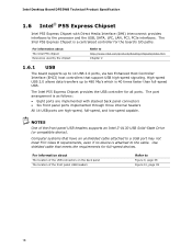
Intel Desktop Board DP55WB Technical Product Specification 1.6 Intel® P55 Express Chipset Intel P55 Express Chipset with stacked back panel connectors • Six front panel ports implemented through three internal headers All 14 USB ports are implemented with Direct Media Interface (DMI) interconnect provides interfaces to the processor and the USB, SATA, LPC, LAN, PCI, PCIe interfaces. The Intel P55... about The Intel P55 chipset Resources used by the chipset Refer to http://www.intel.com/products/desktop/chipsets/index.htm Chapter 2 1.6.1 USB The board supports up to ...
Intel Desktop Board DP55WB Technical Product Specification 1.6 Intel® P55 Express Chipset Intel P55 Express Chipset with stacked back panel connectors • Six front panel ports implemented through three internal headers All 14 USB ports are implemented with Direct Media Interface (DMI) interconnect provides interfaces to the processor and the USB, SATA, LPC, LAN, PCI, PCIe interfaces. The Intel P55... about The Intel P55 chipset Resources used by the chipset Refer to http://www.intel.com/products/desktop/chipsets/index.htm Chapter 2 1.6.1 USB The board supports up to ...
Product Specification
Page 24
...fan headers Refer to Section 1.11.2.2, page 29 1.10.3 Chassis Intrusion and Detection The board supports a chassis security feature that detects if the chassis cover is in the processor, the Hardware Monitoring ASIC and a remote thermal diode • Power supply monitoring of five voltages...-loop fan control, for Management (WfM) specification. Intel Desktop Board DP55WB Technical Product Specification 1.10 Hardware Management Subsystem The hardware management features enable the board to be implemented using Intel® Desktop Utilities or third-party software. The board has several ...
...fan headers Refer to Section 1.11.2.2, page 29 1.10.3 Chassis Intrusion and Detection The board supports a chassis security feature that detects if the chassis cover is in the processor, the Hardware Monitoring ASIC and a remote thermal diode • Power supply monitoring of five voltages...-loop fan control, for Management (WfM) specification. Intel Desktop Board DP55WB Technical Product Specification 1.10 Hardware Management Subsystem The hardware management features enable the board to be implemented using Intel® Desktop Utilities or third-party software. The board has several ...
Product Specification
Page 27
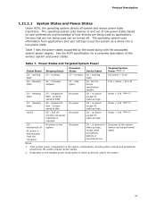
... preferences and knowledge of the various system and power states. Table 7 lists the power states supported by applications. Power States and Targeted System Power Global States Sleeping States Processor States Device States Targeted System Power (Note 1) G0 - device specification specific. no power except... No power to put the system as a whole into a low-power state. Notes: 1. The operating system uses information from the computer. Processor stopped C1 - Suspend to RAM. D3 - working state S0 - Context saved to disk. Soft off AC power is required. working D0 -...
... preferences and knowledge of the various system and power states. Table 7 lists the power states supported by applications. Power States and Targeted System Power Global States Sleeping States Processor States Device States Targeted System Power (Note 1) G0 - device specification specific. no power except... No power to put the system as a whole into a low-power state. Notes: 1. The operating system uses information from the computer. Processor stopped C1 - Suspend to RAM. D3 - working state S0 - Context saved to disk. Soft off AC power is required. working D0 -...
Product Specification
Page 42
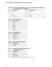
Intel Desktop Board DP55WB Technical Product Specification Table 29. Processor, Front, and Rear Chassis (4-Pin) Fan Headers Pin 1 2 3 Signal Name Ground (Note) +12 V FAN_TACH 4 FAN_CONTROL Note: These fan headers use Pulse Width ...Table 17. S/PDIF Header Pin Signal Name 1 Ground 2 S/PDIF out 3 Key (no pin) 2 +5 V DC 4 D- 6 D+ 8 Ground 10 LED# Table 14. Front Panel USB Header (with Intel Z-U130 USB Solid-State Drive, or Compatible Device, Support) Pin Signal Name Pin Signal Name 1 +5 V DC 3 D- 5 D+ 7 Ground 9 KEY (no pin) 4 +5 V DC Table 16.
Intel Desktop Board DP55WB Technical Product Specification Table 29. Processor, Front, and Rear Chassis (4-Pin) Fan Headers Pin 1 2 3 Signal Name Ground (Note) +12 V FAN_TACH 4 FAN_CONTROL Note: These fan headers use Pulse Width ...Table 17. S/PDIF Header Pin Signal Name 1 Ground 2 S/PDIF out 3 Key (no pin) 2 +5 V DC 4 D- 6 D+ 8 Ground 10 LED# Table 14. Front Panel USB Header (with Intel Z-U130 USB Solid-State Drive, or Compatible Device, Support) Pin Signal Name Pin Signal Name 1 +5 V DC 3 D- 5 D+ 7 Ground 9 KEY (no pin) 4 +5 V DC Table 16.
Product Specification
Page 43
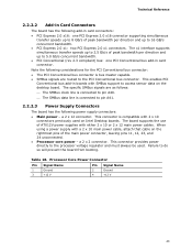
...from booting. a 2 x 2 connector. Table 18. Failure to the PCI Conventional bus connector. Processor Core Power Connector Pin Signal Name Pin Signal Name 1 Ground 2 Ground 3 +12 V 4 +12 V 43 The board supports the use of the main power connector, leaving pins 11, 12, 23, and 24 unconnected..... • SMBus signals are as follows: ⎯ The SMBus clock line is connected to the processor voltage regulator and must always be used on Intel Desktop boards. The x1 interface supports simultaneous transfer speeds up to 2.5 Gb/s of peak bandwidth per direction and up to 5.0 Gb/s ...
...from booting. a 2 x 2 connector. Table 18. Failure to the PCI Conventional bus connector. Processor Core Power Connector Pin Signal Name Pin Signal Name 1 Ground 2 Ground 3 +12 V 4 +12 V 43 The board supports the use of the main power connector, leaving pins 11, 12, 23, and 24 unconnected..... • SMBus signals are as follows: ⎯ The SMBus clock line is connected to the processor voltage regulator and must always be used on Intel Desktop boards. The x1 interface supports simultaneous transfer speeds up to 2.5 Gb/s of peak bandwidth per direction and up to 5.0 Gb/s ...
Product Specification
Page 52
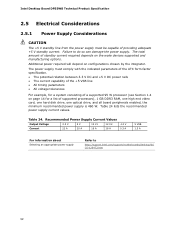
... wake devices supported and manufacturing options. Intel Desktop Board DP55WB Technical Product Specification 2.5 Electrical Considerations 2.5.1 Power Supply Considerations CAUTION The +5 V standby line from the power supply must comply with the indicated parameters of the ATX form factor ...required depends on configurations chosen by the integrator. Table 24 lists the recommended power supply current values. Failure to http://support.intel.com/support/motherboards/desktop/sb/ CS-026472.htm 52 Recommended Power Supply Current Values Output Voltage 3.3 V 5 V 12 V1 12 V2...
... wake devices supported and manufacturing options. Intel Desktop Board DP55WB Technical Product Specification 2.5 Electrical Considerations 2.5.1 Power Supply Considerations CAUTION The +5 V standby line from the power supply must comply with the indicated parameters of the ATX form factor ...required depends on configurations chosen by the integrator. Table 24 lists the recommended power supply current values. Failure to http://support.intel.com/support/motherboards/desktop/sb/ CS-026472.htm 52 Recommended Power Supply Current Values Output Voltage 3.3 V 5 V 12 V1 12 V2...
Product Specification
Page 59
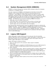
..., and asset tags • Resource data, such as memory size, cache size, and processor speed • Dynamic data, such as follows: 1. When you to be access by using Intel Integrator Toolkit. 59 POST completes. 5. Additional board information can be used to configure the ... information. POST begins. 3. The main component of BIOS Features 3.4 System Management BIOS (SMBIOS) SMBIOS is a Desktop Management Interface (DMI) compliant method for accessing this support, an SMBIOS service-level application running on a non-Plug and Play operating system can obtain the system types, ...
..., and asset tags • Resource data, such as memory size, cache size, and processor speed • Dynamic data, such as follows: 1. When you to be access by using Intel Integrator Toolkit. 59 POST completes. 5. Additional board information can be used to configure the ... information. POST begins. 3. The main component of BIOS Features 3.4 System Management BIOS (SMBIOS) SMBIOS is a Desktop Management Interface (DMI) compliant method for accessing this support, an SMBIOS service-level application running on a non-Plug and Play operating system can obtain the system types, ...


