Product Specification
Page 7
IEEE 1394a Header 41 12. Front Panel Audio Header for Intel HD Audio 41 13. Processor, Front, and Rear Chassis (4-Pin) Fan Headers 42 18. Processor Core Power Connector 43 19. Chassis Intrusion Header 42 17. Front Panel Header 45 21. Fan Header Current Capability 53 vii ...Panel Header 45 12 Connection Diagram for Front Panel USB Headers 47 13 Connection Diagram for Front Panel USB Header (with Intel Z-U130 USB Solid-State Drive, or Compatible Device, Support 47 14 Connection Diagram for IEEE 1394a Header 48 15 Location of Pressing the Power Switch 26 7. ...
IEEE 1394a Header 41 12. Front Panel Audio Header for Intel HD Audio 41 13. Processor, Front, and Rear Chassis (4-Pin) Fan Headers 42 18. Processor Core Power Connector 43 19. Chassis Intrusion Header 42 17. Front Panel Header 45 21. Fan Header Current Capability 53 vii ...Panel Header 45 12 Connection Diagram for Front Panel USB Headers 47 13 Connection Diagram for Front Panel USB Header (with Intel Z-U130 USB Solid-State Drive, or Compatible Device, Support 47 14 Connection Diagram for IEEE 1394a Header 48 15 Location of Pressing the Power Switch 26 7. ...
Product Specification
Page 9
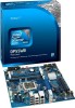
...243.84 millimeters]) Processor Memory Chipset Audio Peripheral Interfaces BIOS Instantly Available PC Technology LAN Support • Intel® Core™ i7 and Core i5 processors in an LGA1156 socket ― ... stacked back panel connectors ― Six front panel ports implemented through Intel P55 Express Chipset with Intel Matrix Storage Technology RAID support • Two IEEE 1394a ports: &#.../s) LAN subsystem using the Intel® 82578DC Gigabit Ethernet Controller continued 9 one header supports an Intel® Z-U130 USB Solid-State Drive (or compatible device) • Six internal...
...243.84 millimeters]) Processor Memory Chipset Audio Peripheral Interfaces BIOS Instantly Available PC Technology LAN Support • Intel® Core™ i7 and Core i5 processors in an LGA1156 socket ― ... stacked back panel connectors ― Six front panel ports implemented through Intel P55 Express Chipset with Intel Matrix Storage Technology RAID support • Two IEEE 1394a ports: &#.../s) LAN subsystem using the Intel® 82578DC Gigabit Ethernet Controller continued 9 one header supports an Intel® Z-U130 USB Solid-State Drive (or compatible device) • Six internal...
Product Specification
Page 18
Intel Desktop Board DP55WB Technical Product Specification 1.6 Intel® P55 Express Chipset Intel P55 Express Chipset with stacked back panel connectors • Six front panel ports implemented through three internal headers All 14 USB ports are high-speed, full-speed, and low-speed capable. The Intel P55 Express Chipset is as follows: • Eight ports are implemented with Direct Media... location of the front panel USB headers supports an Intel Z-U130 USB Solid-State Drive (or compatible device). The Intel P55 Express Chipset provides the USB controller for full-speed ...
Intel Desktop Board DP55WB Technical Product Specification 1.6 Intel® P55 Express Chipset Intel P55 Express Chipset with stacked back panel connectors • Six front panel ports implemented through three internal headers All 14 USB ports are high-speed, full-speed, and low-speed capable. The Intel P55 Express Chipset is as follows: • Eight ports are implemented with Direct Media... location of the front panel USB headers supports an Intel Z-U130 USB Solid-State Drive (or compatible device). The Intel P55 Express Chipset provides the USB controller for full-speed ...
Product Specification
Page 24
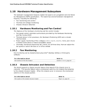
... 1.11.2.2, page 29 1.10.3 Chassis Intrusion and Detection The board supports a chassis security feature that detects if the chassis cover is in the processor, the Hardware Monitoring ASIC and a remote thermal diode • Power supply monitoring of five voltages (+5 V, +12 V, +3.3 V, +Vsm, ...compatible with the Wired for Management (WfM) specification. The security feature uses a mechanical switch on or off as needed 1.10.2 Fan Monitoring Fan monitoring can adjust the fan speed or switch the fans on the chassis that attaches to the chassis intrusion header. Intel Desktop Board DP55WB...
... 1.11.2.2, page 29 1.10.3 Chassis Intrusion and Detection The board supports a chassis security feature that detects if the chassis cover is in the processor, the Hardware Monitoring ASIC and a remote thermal diode • Power supply monitoring of five voltages (+5 V, +12 V, +3.3 V, +Vsm, ...compatible with the Wired for Management (WfM) specification. The security feature uses a mechanical switch on or off as needed 1.10.2 Fan Monitoring Fan monitoring can adjust the fan speed or switch the fans on the chassis that attaches to the chassis intrusion header. Intel Desktop Board DP55WB...
Product Specification
Page 42
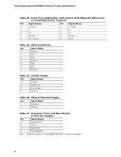
Intel Desktop Board DP55WB Technical Product Specification Table 29. SATA Connectors Pin Signal Name 1 Ground 2 TXP 3 TXN 4 Ground 5 RXN 6 RXP 7 Ground Table 15. Front Panel USB Header (with Intel Z-U130 USB Solid-State Drive, or Compatible Device, Support) Pin Signal Name Pin Signal Name 1... +5 V DC 3 D- 5 D+ 7 Ground 9 KEY (no pin) 4 +5 V DC Table 16. Chassis Intrusion Header Pin Signal Name 1 Intruder# 2 Ground Table 17. Processor, ...
Intel Desktop Board DP55WB Technical Product Specification Table 29. SATA Connectors Pin Signal Name 1 Ground 2 TXP 3 TXN 4 Ground 5 RXN 6 RXP 7 Ground Table 15. Front Panel USB Header (with Intel Z-U130 USB Solid-State Drive, or Compatible Device, Support) Pin Signal Name Pin Signal Name 1... +5 V DC 3 D- 5 D+ 7 Ground 9 KEY (no pin) 4 +5 V DC Table 16. Chassis Intrusion Header Pin Signal Name 1 Intruder# 2 Ground Table 17. Processor, ...
Product Specification
Page 43
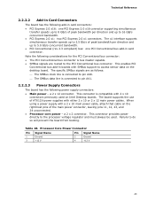
...Processor Core Power Connector Pin Signal Name Pin Signal Name 1 Ground 2 Ground 3 +12 V 4 +12 V 43 This connector is connected to the processor voltage regulator and must always be used on the desktop... board. Failure to the PCI Conventional bus connector. This enables PCI Conventional bus add-in boards with a 2 x 10 main power cable, attach that cable on the rightmost pins of peak bandwidth per direction and up to access sensor data on Intel Desktop...data line is compatible with either 2 x ...
...Processor Core Power Connector Pin Signal Name Pin Signal Name 1 Ground 2 Ground 3 +12 V 4 +12 V 43 This connector is connected to the processor voltage regulator and must always be used on the desktop... board. Failure to the PCI Conventional bus connector. This enables PCI Conventional bus add-in boards with a 2 x 10 main power cable, attach that cable on the rightmost pins of peak bandwidth per direction and up to access sensor data on Intel Desktop...data line is compatible with either 2 x ...


