Product Specification
Page 2
... deviate from published specifications. Intel, Core i7, and Core i5 are evaluated as the property of Intel Corporation or its subsidiaries in the Intel Desktop Board DP55WB Specification Update before placing your distributor to only the standard Intel® Desktop Board DP55WB with BIOS identifier WBIBX10J.86A. Contact your local Intel sales office or your product order. All Intel® desktop boards are registered trademarks of...
... deviate from published specifications. Intel, Core i7, and Core i5 are evaluated as the property of Intel Corporation or its subsidiaries in the Intel Desktop Board DP55WB Specification Update before placing your distributor to only the standard Intel® Desktop Board DP55WB with BIOS identifier WBIBX10J.86A. Contact your local Intel sales office or your product order. All Intel® desktop boards are registered trademarks of...
Product Specification
Page 3
... general audiences. It is intended to provide detailed, technical information about the conventions used on the Intel Desktop Board DP55WB A map of the resources of the Intel Desktop Board The features supported by the BIOS Setup program A description of the BIOS error messages, beep codes, and POST codes Regulatory compliance and battery disposal information Typographical Conventions This...
... general audiences. It is intended to provide detailed, technical information about the conventions used on the Intel Desktop Board DP55WB A map of the resources of the Intel Desktop Board The features supported by the BIOS Setup program A description of the BIOS error messages, beep codes, and POST codes Regulatory compliance and battery disposal information Typographical Conventions This...
Product Specification
Page 6
Intel Desktop Board DP55WB Technical Product Specification 2.5 Electrical Considerations 52 2.5.1 Power Supply Considerations 52 2.5.2 Fan Header Current Capability 53 2.5.3 Add-in Board Considerations 53 2.6 Thermal Considerations 53 2.7 Reliability 56 2.8 Environmental 56 3 Overview of BIOS Features 3.1 Introduction 57 3.2 BIOS Flash Memory Organization 58 3.3 Resource Configuration 58 3.3.1 PCI Autoconfiguration 58 3.4 System Management BIOS (SMBIOS 59 3.5 Legacy USB Support 59...
Intel Desktop Board DP55WB Technical Product Specification 2.5 Electrical Considerations 52 2.5.1 Power Supply Considerations 52 2.5.2 Fan Header Current Capability 53 2.5.3 Add-in Board Considerations 53 2.6 Thermal Considerations 53 2.7 Reliability 56 2.8 Environmental 56 3 Overview of BIOS Features 3.1 Introduction 57 3.2 BIOS Flash Memory Organization 58 3.3 Resource Configuration 58 3.3.1 PCI Autoconfiguration 58 3.4 System Management BIOS (SMBIOS 59 3.5 Legacy USB Support 59...
Product Specification
Page 7
... 8. System Memory Map 37 10. Front Panel Audio Header for Intel HD Audio 41 13. Processor Core Power Connector 43 19. Wake-up Devices and Events 28 9. Component-side Connectors and Headers Shown in Figure 1 12 3. BIOS Setup Configuration Jumper Settings 50 24. Feature Summary 9 2. Front ... Front Panel Header 45 12 Connection Diagram for Front Panel USB Headers 47 13 Connection Diagram for Front Panel USB Header (with Intel Z-U130 USB Solid-State Drive, or Compatible Device, Support 47 14 Connection Diagram for IEEE 1394a Header 48 15 Location of ...
... 8. System Memory Map 37 10. Front Panel Audio Header for Intel HD Audio 41 13. Processor Core Power Connector 43 19. Wake-up Devices and Events 28 9. Component-side Connectors and Headers Shown in Figure 1 12 3. BIOS Setup Configuration Jumper Settings 50 24. Feature Summary 9 2. Front ... Front Panel Header 45 12 Connection Diagram for Front Panel USB Headers 47 13 Connection Diagram for Front Panel USB Header (with Intel Z-U130 USB Solid-State Drive, or Compatible Device, Support 47 14 Connection Diagram for IEEE 1394a Header 48 15 Location of ...
Product Specification
Page 8
... Program Menu Bar 58 29. Acceptable Drives/Media Types for Components 55 27. Port 80h POST Code Ranges 69 37. BIOS Setup Program Function Keys 58 30. Supervisor and User Password Functions 64 33. EMC Regulations 81 42. BIOS Beep Codes 67 34. Typical Port 80h POST Sequence 73 39. Lead-Free Board.... Boot Device Menu Options 62 32. Front-panel Power LED Blink Codes 68 35. Port 80h POST Codes 70 38. Product Certification Markings 82 viii Intel Desktop Board DP55WB Technical Product Specification 26. BIOS Error Messages 68 36. Safety Standards 75 40.
... Program Menu Bar 58 29. Acceptable Drives/Media Types for Components 55 27. Port 80h POST Code Ranges 69 37. BIOS Setup Program Function Keys 58 30. Supervisor and User Password Functions 64 33. EMC Regulations 81 42. BIOS Beep Codes 67 34. Typical Port 80h POST Sequence 73 39. Lead-Free Board.... Boot Device Menu Options 62 32. Front-panel Power LED Blink Codes 68 35. Port 80h POST Codes 70 38. Product Certification Markings 82 viii Intel Desktop Board DP55WB Technical Product Specification 26. BIOS Error Messages 68 36. Safety Standards 75 40.
Product Specification
Page 9
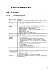
... inches [243.84 millimeters by 243.84 millimeters]) Processor Memory Chipset Audio Peripheral Interfaces BIOS Instantly Available PC Technology LAN Support • Intel® Core™ i7 and Core i5 processors in the SPI Flash device • Support for Advanced Configuration and Power Interface ... interfaces through Intel P55 Express Chipset with Intel Matrix Storage Technology RAID support • Two IEEE 1394a ports: ― One port via a back panel connector ― One port via an internal header for front panel cabling • Intel® BIOS resident in an LGA1156 socket ―...
... inches [243.84 millimeters by 243.84 millimeters]) Processor Memory Chipset Audio Peripheral Interfaces BIOS Instantly Available PC Technology LAN Support • Intel® Core™ i7 and Core i5 processors in the SPI Flash device • Support for Advanced Configuration and Power Interface ... interfaces through Intel P55 Express Chipset with Intel Matrix Storage Technology RAID support • Two IEEE 1394a ports: ― One port via a back panel connector ― One port via an internal header for front panel cabling • Intel® BIOS resident in an LGA1156 socket ―...
Product Specification
Page 10
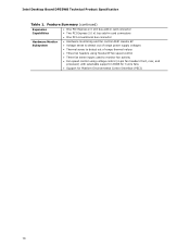
... sense inputs used to monitor fan activity • Fan speed control using voltage control (4-pin fan headers front, rear, and processor) with selectable support in BIOS for 3 wire fans • Support for Platform Environmental Control Interface (PECI) 10 Intel Desktop Board DP55WB Technical Product Specification Table 1.
... sense inputs used to monitor fan activity • Fan speed control using voltage control (4-pin fan headers front, rear, and processor) with selectable support in BIOS for 3 wire fans • Support for Platform Environmental Control Interface (PECI) 10 Intel Desktop Board DP55WB Technical Product Specification Table 1.
Product Specification
Page 12
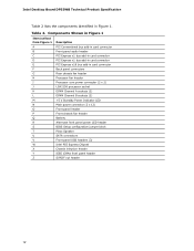
...Intel Desktop Board DP55WB Technical Product Specification Table 2 lists the components identified in card connector Back panel connectors Rear chassis fan header Processor fan header Processor core power connector (2 x 2) LGA1156 ...processor socket DIMM Channel A sockets (2) DIMM Channel B sockets (2) +5 V Standby Power Indicator LED Main power connector (2 x 12) Front panel header Front chassis fan header Battery Alternate front panel power LED header BIOS Setup configuration jumper block Piezo Speaker SATA connectors Front panel USB headers (3) Intel P55...
...Intel Desktop Board DP55WB Technical Product Specification Table 2 lists the components identified in card connector Back panel connectors Rear chassis fan header Processor fan header Processor core power connector (2 x 2) LGA1156 ...processor socket DIMM Channel A sockets (2) DIMM Channel B sockets (2) +5 V Standby Power Indicator LED Main power connector (2 x 12) Front panel header Front chassis fan header Battery Alternate front panel power LED header BIOS Setup configuration jumper block Piezo Speaker SATA connectors Front panel USB headers (3) Intel P55...
Product Specification
Page 14
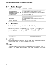
... the Intel Core i7 and Core i5 processors in an LGA1156 socket Other processors may be supported in the future. See the Intel web site listed below for this World Wide Web site: http://www.intel.com/products/motherboard/DP55WB/index.htm http://support.intel.com/support/motherboards/desktop http://www.intel.com/products/motherboard/DP55WB/index.htm http://processormatch.intel.com http://www.intel.com/products/desktop/chipsets...
... the Intel Core i7 and Core i5 processors in an LGA1156 socket Other processors may be supported in the future. See the Intel web site listed below for this World Wide Web site: http://www.intel.com/products/motherboard/DP55WB/index.htm http://support.intel.com/support/motherboards/desktop http://www.intel.com/products/motherboard/DP55WB/index.htm http://processormatch.intel.com http://www.intel.com/products/desktop/chipsets...
Product Specification
Page 15
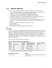
... 8 16 Note: "DS" refers to double-sided memory modules (containing two rows of SDRAM). If non-SPD memory is installed, the BIOS will attempt to correctly configure the memory settings, but performance and reliability may be populated with 2 Gb memory technology). Product Description 1.5 System Memory... the BIOS to read the SPD data and program the chipset to single-sided memory modules (containing one row of SDRAM) and "SS" refers to accurately configure memory settings for optimum performance. Tested Memory Refer to: http://support.intel.com/support/motherboards/desktop/sb/...
... 8 16 Note: "DS" refers to double-sided memory modules (containing two rows of SDRAM). If non-SPD memory is installed, the BIOS will attempt to correctly configure the memory settings, but performance and reliability may be populated with 2 Gb memory technology). Product Description 1.5 System Memory... the BIOS to read the SPD data and program the chipset to single-sided memory modules (containing one row of SDRAM) and "SS" refers to accurately configure memory settings for optimum performance. Tested Memory Refer to: http://support.intel.com/support/motherboards/desktop/sb/...
Product Specification
Page 19
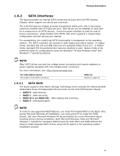
... Both Microsoft Windows Vista and Microsoft Windows 7 include the necessary RAID drivers for configurations using the F6 switch in the BIOS. For compatibility, the underlying SATA functionality is used for a maximum of six SATA devices. distributed parity NOTE In order...8226; RAID 5 - Also, during installation. The Intel P55 Express Chipset provides independent SATA ports with low-voltage power connectors. Product Description 1.6.2 SATA Interfaces The board provides six internal SATA connectors through the Intel P55 Express Chipset, which provides the following RAID (Redundant...
... Both Microsoft Windows Vista and Microsoft Windows 7 include the necessary RAID drivers for configurations using the F6 switch in the BIOS. For compatibility, the underlying SATA functionality is used for a maximum of six SATA devices. distributed parity NOTE In order...8226; RAID 5 - Also, during installation. The Intel P55 Express Chipset provides independent SATA ports with low-voltage power connectors. Product Description 1.6.2 SATA Interfaces The board provides six internal SATA connectors through the Intel P55 Express Chipset, which provides the following RAID (Redundant...
Product Specification
Page 20
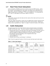
... Ctrl panel Default Line In Rear Surround (Stereo 2) Center/Sub (Stereo 3) Default Ctrl panel Ctrl panel 20 Green Front panel - Intel Desktop Board DP55WB Technical Product Specification 1.7 Real-Time Clock Subsystem A coin-cell battery (CR2032) powers the real-time clock and CMOS memory. When the ...voltage drops below a certain level, the BIOS Setup program settings stored in , the standby current from the power supply extends the ...
... Ctrl panel Default Line In Rear Surround (Stereo 2) Center/Sub (Stereo 3) Default Ctrl panel Ctrl panel 20 Green Front panel - Intel Desktop Board DP55WB Technical Product Specification 1.7 Real-Time Clock Subsystem A coin-cell battery (CR2032) powers the real-time clock and CMOS memory. When the ...voltage drops below a certain level, the BIOS Setup program settings stored in , the standby current from the power supply extends the ...
Product Specification
Page 29
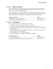
... returns to Figure 10, page 39 Table 19, page 44 1.11.2.2 Fan Headers The function/operation of the fan headers is off or in the BIOS Setup program's Boot menu. For information about The location of the main power connector The signal names of the main power connector Refer to the...
... returns to Figure 10, page 39 Table 19, page 44 1.11.2.2 Fan Headers The function/operation of the fan headers is off or in the BIOS Setup program's Boot menu. For information about The location of the main power connector The signal names of the main power connector Refer to the...
Product Specification
Page 31
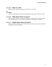
NOTE Wake from USB requires the use of a USB peripheral that supports Wake from USB. 1.11.2.6 PME# Signal Wake-up Support When the PME# signal on the PCI Conventional bus is asserted, the computer wakes from an ACPI S1, S3, S4, or S5 state (with Wake on PME enabled in the BIOS). 1.11.2.7 WAKE# Signal Wake-up Support When the WAKE# signal on the PCI Express bus is asserted, the computer wakes from ACPI S1 or S3 states. Product Description 1.11.2.5 Wake from USB USB bus activity wakes the computer from an ACPI S1, S3, S4, or S5 state. 31
NOTE Wake from USB requires the use of a USB peripheral that supports Wake from USB. 1.11.2.6 PME# Signal Wake-up Support When the PME# signal on the PCI Conventional bus is asserted, the computer wakes from an ACPI S1, S3, S4, or S5 state (with Wake on PME enabled in the BIOS). 1.11.2.7 WAKE# Signal Wake-up Support When the WAKE# signal on the PCI Express bus is asserted, the computer wakes from ACPI S1 or S3 states. Product Description 1.11.2.5 Wake from USB USB bus activity wakes the computer from an ACPI S1, S3, S4, or S5 state. 31
Product Specification
Page 35
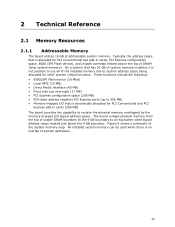
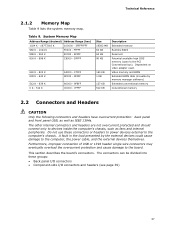
...due to system address space being allocated for other system critical functions. These functions include the following: • BIOS/SPI Flash device (16 Mbit) • Local APIC (19 MB) • Direct Media Interface (40 MB) • Front side bus interrupts (17 MB) • PCI Express configuration space (256... to use all of system memory installed, it is dynamically allocated for PCI Conventional bus add-in cards, PCI Express configuration space, BIOS (SPI Flash device), and chipset overhead resides above the 4 GB boundary. Typically the address space that is not possible to reclaim ...
...due to system address space being allocated for other system critical functions. These functions include the following: • BIOS/SPI Flash device (16 Mbit) • Local APIC (19 MB) • Direct Media Interface (40 MB) • Front side bus interrupts (17 MB) • PCI Express configuration space (256... to use all of system memory installed, it is dynamically allocated for PCI Conventional bus add-in cards, PCI Express configuration space, BIOS (SPI Flash device), and chipset overhead resides above the 4 GB boundary. Typically the address space that is not possible to reclaim ...
Product Specification
Page 37
... Range (decimal) Address Range (hex) 1024 K - 16777216 K 100000 - 3FFFFFFFF 960 K - 1024 K F0000 - DFFFF 640 K - 800 K 639 K - 640 K 512 K - 639 K 0 K - 512 K A0000 - Video memory and BIOS Extended BIOS data (movable by the external devices could cause damage to the computer's chassis. A fault in the load presented by memory manager software) Extended conventional memory...- 9FFFF 80000 - 9FBFF 00000 - 7FFFF Size 16382 MB 64 KB 64 KB 96 KB 160 KB 1 KB 127 KB 512 KB Description Extended memory Runtime BIOS Reserved Potential available high DOS memory (open to the board. Table 9.
... Range (decimal) Address Range (hex) 1024 K - 16777216 K 100000 - 3FFFFFFFF 960 K - 1024 K F0000 - DFFFF 640 K - 800 K 639 K - 640 K 512 K - 639 K 0 K - 512 K A0000 - Video memory and BIOS Extended BIOS data (movable by the external devices could cause damage to the computer's chassis. A fault in the load presented by memory manager software) Extended conventional memory...- 9FFFF 80000 - 9FBFF 00000 - 7FFFF Size 16382 MB 64 KB 64 KB 96 KB 160 KB 1 KB 127 KB 512 KB Description Extended memory Runtime BIOS Reserved Potential available high DOS memory (open to the board. Table 9.
Product Specification
Page 49
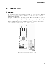
..., the board could be damaged. When the jumper is set to configure mode and the computer is powered-up, the BIOS compares the processor version and the microcode version in the BIOS and reports if the two match. Always turn off the power and unplug the power cord from the computer before...
..., the board could be damaged. When the jumper is set to configure mode and the computer is powered-up, the BIOS compares the processor version and the microcode version in the BIOS and reports if the two match. Always turn off the power and unplug the power cord from the computer before...
Product Specification
Page 50
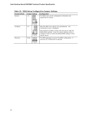
... A recovery CD or flash drive is displayed. Intel Desktop Board DP55WB Technical Product Specification Table 23. Note that this Configure mode is the only way to their default values. Press F9 (restore defaults) while in Configure mode to restore the BIOS/CMOS settings to clear the BIOS/CMOS settings. Configure 2-3 Recovery None After the POST...
... A recovery CD or flash drive is displayed. Intel Desktop Board DP55WB Technical Product Specification Table 23. Note that this Configure mode is the only way to their default values. Press F9 (restore defaults) while in Configure mode to restore the BIOS/CMOS settings to clear the BIOS/CMOS settings. Configure 2-3 Recovery None After the POST...
Product Specification
Page 55
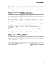
... the component corresponds to cool the board. Maximum case temperatures are sensitive to Section 1.3, page 14 http://www.intel.com/products/desktop/ chipsets/ 55 The surface temperature at or below the Maximum Case Temperature. Thermal Considerations for Components Component Maximum... the temperature measurement in the system BIOS is a value reported by the components). Table 26. Tcontrol Values for Components Component Tcontrol Processor For processor case temperature, see processor datasheets and processor specification updates Intel P55 Express Chipset 111 oC To ensure ...
... the component corresponds to cool the board. Maximum case temperatures are sensitive to Section 1.3, page 14 http://www.intel.com/products/desktop/ chipsets/ 55 The surface temperature at or below the Maximum Case Temperature. Thermal Considerations for Components Component Maximum... the temperature measurement in the system BIOS is a value reported by the components). Table 26. Tcontrol Values for Components Component Tcontrol Processor For processor case temperature, see processor datasheets and processor specification updates Intel P55 Express Chipset 111 oC To ensure ...
Product Specification
Page 57
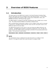
... 57 Maintenance Main Advanced Performance Security Power Boot Exit NOTE The maintenance menu is displayed only when the board is powered-up, the BIOS compares the CPU version and the microcode version in the Serial Peripheral Interface Flash Memory (SPI Flash) and can be updated using ...a disk-based program. The BIOS displays a message during POST identifying the type of BIOS Features 3.1 Introduction The board uses an Intel BIOS that is stored in the BIOS and reports if the two match. When the BIOS Setup configuration jumper is set to view and change the...
... 57 Maintenance Main Advanced Performance Security Power Boot Exit NOTE The maintenance menu is displayed only when the board is powered-up, the BIOS compares the CPU version and the microcode version in the Serial Peripheral Interface Flash Memory (SPI Flash) and can be updated using ...a disk-based program. The BIOS displays a message during POST identifying the type of BIOS Features 3.1 Introduction The board uses an Intel BIOS that is stored in the BIOS and reports if the two match. When the BIOS Setup configuration jumper is set to view and change the...


