Product Guide
Page 5
...Desktop Board Features Supported Operating Systems 10 Desktop Board Components 11 Processor ...13 Main Memory...13 Intel® P35 Express Chipset 14 Audio Subsystem 15 Legacy Input/Output (I/O) Controller 15 LAN Subsystem 16 RJ-45 LAN Connector LEDs 16 Hi-Speed USB 2.0 Support 17 Enhanced IDE Interface 17 Serial ATA...18 Serial ATA RAID 18 Intel...® Rapid Recover Technology 18 Expandability...18 BIOS ...19 Serial ATA and IDE Auto Configuration 19 PCI and PCI Express* Auto Configuration 19 Security Passwords 19 Hardware Management...
...Desktop Board Features Supported Operating Systems 10 Desktop Board Components 11 Processor ...13 Main Memory...13 Intel® P35 Express Chipset 14 Audio Subsystem 15 Legacy Input/Output (I/O) Controller 15 LAN Subsystem 16 RJ-45 LAN Connector LEDs 16 Hi-Speed USB 2.0 Support 17 Enhanced IDE Interface 17 Serial ATA...18 Serial ATA RAID 18 Intel...® Rapid Recover Technology 18 Expandability...18 BIOS ...19 Serial ATA and IDE Auto Configuration 19 PCI and PCI Express* Auto Configuration 19 Security Passwords 19 Hardware Management...
Product Guide
Page 6
Intel Desktop Board DP35DP Product Guide Installing a Processor 29 Installing the Processor Fan Heat Sink 32 Connecting the Processor Fan Heat Sink Cable 33 Removing the Processor 34 Installing ... Channel Memory Configuration 35 Two or Four DIMMs 35 Three DIMMs 36 Installing DIMMs 37 Removing DIMMs 39 Installing and Removing a PCI Express x16 Card 40 Installing a PCI Express x16 Card 40 Removing the PCI Express x16 Card 41 Connecting the IDE Cable 42 Connecting the Serial ATA (SATA) Cables 44 Installing the External Serial ATA...
Intel Desktop Board DP35DP Product Guide Installing a Processor 29 Installing the Processor Fan Heat Sink 32 Connecting the Processor Fan Heat Sink Cable 33 Removing the Processor 34 Installing ... Channel Memory Configuration 35 Two or Four DIMMs 35 Three DIMMs 36 Installing DIMMs 37 Removing DIMMs 39 Installing and Removing a PCI Express x16 Card 40 Installing a PCI Express x16 Card 40 Removing the PCI Express x16 Card 41 Connecting the IDE Cable 42 Connecting the Serial ATA (SATA) Cables 44 Installing the External Serial ATA...
Product Guide
Page 7
...vii Lift the Socket Lever 29 7. Close the Load Plate 32 12. Dual Channel Memory Configuration with Two DIMMs 35 14. Desktop Board DP35DP Mounting Screw Hole Locations 28 6. Dual Channel Memory Configuration with Three DIMMs 36 16. Back Panel Audio Connectors 51 25. ... a DIMM 38 18. Removing a PCI Express x16 Card 41 20. LAN Connector LEDs 16 3. Use DDR2 DIMMs 37 17. Remove the Protective Socket Cover 30 9. Lift the Load Plate 30 8. Contents 5 Configuring for Intel® Rapid Recover Technology Enabling Intel Rapid Recover Technology 67 Creating a Recovery...
...vii Lift the Socket Lever 29 7. Close the Load Plate 32 12. Dual Channel Memory Configuration with Two DIMMs 35 14. Desktop Board DP35DP Mounting Screw Hole Locations 28 6. Dual Channel Memory Configuration with Three DIMMs 36 16. Back Panel Audio Connectors 51 25. ... a DIMM 38 18. Removing a PCI Express x16 Card 41 20. LAN Connector LEDs 16 3. Use DDR2 DIMMs 37 17. Remove the Protective Socket Cover 30 9. Lift the Load Plate 30 8. Contents 5 Configuring for Intel® Rapid Recover Technology Enabling Intel Rapid Recover Technology 67 Creating a Recovery...
Product Guide
Page 9
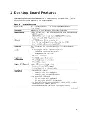
... Intel® 82801IR I/O Controller Hub (ICH9R) One PCI Express* x16 connector supporting PCI Express graphics cards • 8-channel (7.1) onboard subsystem, featuring: ― Intel® High Definition Audio interface ― IDT* STAC9271D audio codec • HD Audio Link header • One PCI Express x16 connector • Three PCI Express x1 connectors • Three PCI... single or dual channel DDR2 SDRAM interface • Support for up to 8 GB of system memory Intel® P35 Express Chipset consisting of Intel® Desktop Board DP35DP. Table 1 summarizes the major features of the...
... Intel® 82801IR I/O Controller Hub (ICH9R) One PCI Express* x16 connector supporting PCI Express graphics cards • 8-channel (7.1) onboard subsystem, featuring: ― Intel® High Definition Audio interface ― IDT* STAC9271D audio codec • HD Audio Link header • One PCI Express x16 connector • Three PCI Express x1 connectors • Three PCI... single or dual channel DDR2 SDRAM interface • Support for up to 8 GB of system memory Intel® P35 Express Chipset consisting of Intel® Desktop Board DP35DP. Table 1 summarizes the major features of the...
Product Guide
Page 10
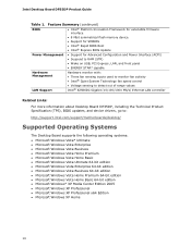
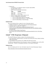
... Support for SMBIOS • Intel® Rapid BIOS Boot • Intel® Express BIOS Update Power Management • Support for Advanced Configuration and Power Interface (ACPI) • Suspend to RAM (STR) • Wake on USB, PCI Express, LAN, and front panel ...LAN controller Related Links: For more information about Desktop Board DP35DP, including the Technical Product Specification (TPS), BIOS updates, and device drivers, go to: http://support.intel.com/support/motherboards/desktop/ Supported Operating Systems The Desktop Board supports the following operating systems: • ...
... Support for SMBIOS • Intel® Rapid BIOS Boot • Intel® Express BIOS Update Power Management • Support for Advanced Configuration and Power Interface (ACPI) • Suspend to RAM (STR) • Wake on USB, PCI Express, LAN, and front panel ...LAN controller Related Links: For more information about Desktop Board DP35DP, including the Technical Product Specification (TPS), BIOS updates, and device drivers, go to: http://support.intel.com/support/motherboards/desktop/ Supported Operating Systems The Desktop Board supports the following operating systems: • ...
Product Guide
Page 14
... (ICH9R) with DMI interconnect The MCH provides interfaces to the processor, memory, PCI Express bus, and the DMI interconnect. Related Links: Go to the following devices: • Intel P35 Express Chipset Memory Controller Hub (MCH) with Direct Media Interface (DMI) interconnect • Intel 82801IR I /O paths. Intel Desktop Board DP35DP Product Guide • Support for: ⎯ Unbuffered, non-registered single or...
... (ICH9R) with DMI interconnect The MCH provides interfaces to the processor, memory, PCI Express bus, and the DMI interconnect. Related Links: Go to the following devices: • Intel P35 Express Chipset Memory Controller Hub (MCH) with Direct Media Interface (DMI) interconnect • Intel 82801IR I /O paths. Intel Desktop Board DP35DP Product Guide • Support for: ⎯ Unbuffered, non-registered single or...
Product Guide
Page 18
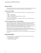
...: • Three PCI Express x1 connectors • One PCI Express x16 connector • Three PCI bus connectors 18 For information on configuring your primary or master drive onto a second hard drive, the recovery drive. Expandability For system expansion, the Desktop Board provides the following RAID... need to your data in the event of your system for Intel Rapid Recover Technology see Chapter 4. data mirroring • RAID 0+1 (or RAID 10) - Intel Desktop Board DP35DP Product Guide Serial ATA The Desktop Board supports six Serial ATA channels (3.0 Gb/s) via any standard SATA...
...: • Three PCI Express x1 connectors • One PCI Express x16 connector • Three PCI bus connectors 18 For information on configuring your primary or master drive onto a second hard drive, the recovery drive. Expandability For system expansion, the Desktop Board provides the following RAID... need to your data in the event of your system for Intel Rapid Recover Technology see Chapter 4. data mirroring • RAID 0+1 (or RAID 10) - Intel Desktop Board DP35DP Product Guide Serial ATA The Desktop Board supports six Serial ATA channels (3.0 Gb/s) via any standard SATA...
Product Guide
Page 19
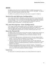
... booting the computer, with the following the instructions on page 55. 19 Desktop Board Features BIOS The BIOS provides the Power-On Self-Test (POST), the BIOS Setup program, the PCI/PCI Express and IDE auto-configuration utilities, and the video BIOS. If only the supervisor...the computer. Security Passwords The BIOS includes security features that restrict whether the BIOS Setup program can be set , you install a PCI/PCI Express add-in card in your computer. A supervisor password and a user password can override the auto-configuration options by following restrictions: &#...
... booting the computer, with the following the instructions on page 55. 19 Desktop Board Features BIOS The BIOS provides the Power-On Self-Test (POST), the BIOS Setup program, the PCI/PCI Express and IDE auto-configuration utilities, and the video BIOS. If only the supervisor...the computer. Security Passwords The BIOS includes security features that restrict whether the BIOS Setup program can be set , you install a PCI/PCI Express add-in card in your computer. A supervisor password and a user password can override the auto-configuration options by following restrictions: &#...
Product Guide
Page 24
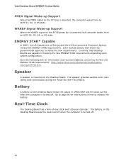
... new requirements. ENERGY STAR* Capable In 2007, the US Department of Energy and the US Environmental Protection Agency revised the ENERGY STAR requirements. Intel Desktop Board DP35DP Product Guide PME# Signal Wake-up Support When the WAKE# signal on the PCI Express bus is asserted, the computer wakes from an ACPI S3, S4, or S5 state.
... new requirements. ENERGY STAR* Capable In 2007, the US Department of Energy and the US Environmental Protection Agency revised the ENERGY STAR requirements. Intel Desktop Board DP35DP Product Guide PME# Signal Wake-up Support When the WAKE# signal on the PCI Express bus is asserted, the computer wakes from an ACPI S3, S4, or S5 state.
Product Guide
Page 25
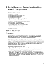
... a station is not available, you can continue to operate even though the front panel power button is off. Some circuitry on the board can provide some ESD protection by wearing an antistatic wrist strap and attaching it to a metal part of the procedures described in this ... This chapter tells you how to: • Install the I/O shield • Install and remove the Desktop Board • Install and remove a processor • Install and remove memory • Install and remove a PCI Express x16 card • Connect the IDE and Serial ATA cables • Install the External SATA (eSATA) ...
... a station is not available, you can continue to operate even though the front panel power button is off. Some circuitry on the board can provide some ESD protection by wearing an antistatic wrist strap and attaching it to a metal part of the procedures described in this ... This chapter tells you how to: • Install the I/O shield • Install and remove the Desktop Board • Install and remove a processor • Install and remove memory • Install and remove a PCI Express x16 card • Connect the IDE and Serial ATA cables • Install the External SATA (eSATA) ...

Product Guide
Page 40
... system. If the card is not fully seated in the PCI Express connector, an electrical short may be damaged. Intel Desktop Board DP35DP Product Guide Installing and Removing a PCI Express x16 Card CAUTION When installing a PCI Express x16 card on the Desktop Board, ensure that the card is fully seated in the PCI Express x16 connector before you power on the over-current protection...
... system. If the card is not fully seated in the PCI Express connector, an electrical short may be damaged. Intel Desktop Board DP35DP Product Guide Installing and Removing a PCI Express x16 Card CAUTION When installing a PCI Express x16 card on the Desktop Board, ensure that the card is fully seated in the PCI Express x16 connector before you power on the over-current protection...

Product Guide
Page 41
Remove the screw (Figure 19, A) that secures the card's metal bracket to remove the PCI Express x16 card from the connector (C). 4. Removing a PCI Express x16 Card 41 Installing and Replacing Desktop Board Components Removing the PCI Express x16 Card Follow these instructions to the chassis back panel. 3. Observe the precautions in the notch. Pull the card straight up. Figure 19. Push the card ejector lever down using the tip of a pencil or similar tool (Figure 19, B) in "Before You Begin" on page 25. 2. This will release the card from the connector: 1.
Remove the screw (Figure 19, A) that secures the card's metal bracket to remove the PCI Express x16 card from the connector (C). 4. Removing a PCI Express x16 Card 41 Installing and Replacing Desktop Board Components Removing the PCI Express x16 Card Follow these instructions to the chassis back panel. 3. Observe the precautions in the notch. Pull the card straight up. Figure 19. Push the card ejector lever down using the tip of a pencil or similar tool (Figure 19, B) in "Before You Begin" on page 25. 2. This will release the card from the connector: 1.

