
Smart Response Technology User Guide
Page 1
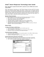
...the value to RAID mode via the system BIOS. Intel® Smart Response Technology caching is implemented as cache memory between the hard disk drive and system memory. Press the F10 key to Configuration > SATA Drives 3. Run the Intel RST software through the All Programs menu or the task... bar icon. 9. System Requirements: For a system to support Intel Smart Response Technology it ...
...the value to RAID mode via the system BIOS. Intel® Smart Response Technology caching is implemented as cache memory between the hard disk drive and system memory. Press the F10 key to Configuration > SATA Drives 3. Run the Intel RST software through the All Programs menu or the task... bar icon. 9. System Requirements: For a system to support Intel Smart Response Technology it ...
Smart Response Technology User Guide
Page 2
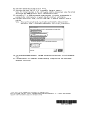
Maximized mode: Acceleration optimized for data protection. Your system is highly recommended to be allocated for the cache memory. and/or other countries. 10. Intel, the Intel logo, Intel Core, and Core Inside are trademarks of others. Select the HDD (or RAID volume) to accelerate the system...system disk for data storage using the simple data single-disk RAID 0 volume that is selected. It is now successfully configured with the Intel Smart Response Technology! * Other names, brands, and logos may be used for maximum performance. 13. Note: Enhanced mode (default): ...
Maximized mode: Acceleration optimized for data protection. Your system is highly recommended to be allocated for the cache memory. and/or other countries. 10. Intel, the Intel logo, Intel Core, and Core Inside are trademarks of others. Select the HDD (or RAID volume) to accelerate the system...system disk for data storage using the simple data single-disk RAID 0 volume that is selected. It is now successfully configured with the Intel Smart Response Technology! * Other names, brands, and logos may be used for maximum performance. 13. Note: Enhanced mode (default): ...

Technical Product Specification
Page 7
... 1.1.1 Feature Summary 11 1.1.2 Board Layout (Top 13 1.1.3 Board Layout (Bottom 15 1.1.4 Block Diagram 16 1.2 Online Support 17 1.3 Processor 17 1.3.1 Graphics Subsystem 18 1.4 System Memory 20 1.4.1 Memory Configurations 21 1.5 Intel® H77 Express Chipset 23 1.5.1 Direct Media Interface (DMI 23 1.5.2 Display Interfaces 23 1.5.3 USB 26 1.5.4 SATA Interfaces 27 1.6 Real-Time Clock Subsystem 29 1.7 Legacy...
... 1.1.1 Feature Summary 11 1.1.2 Board Layout (Top 13 1.1.3 Board Layout (Bottom 15 1.1.4 Block Diagram 16 1.2 Online Support 17 1.3 Processor 17 1.3.1 Graphics Subsystem 18 1.4 System Memory 20 1.4.1 Memory Configurations 21 1.5 Intel® H77 Express Chipset 23 1.5.1 Direct Media Interface (DMI 23 1.5.2 Display Interfaces 23 1.5.3 USB 26 1.5.4 SATA Interfaces 27 1.6 Real-Time Clock Subsystem 29 1.7 Legacy...

Technical Product Specification
Page 8
Intel Desktop Board DH77DF Technical Product Specification 2.3 Jumper Block 59 2.4 Mechanical Considerations 61 2.4.1 Form Factor 61 2.5 Electrical Considerations 62 2.5.1 Power Supply Considerations 62 2.5.2 Power Supervisor 63 2.5.3 Fan Header Current Capability 63 2.5.4 Add-in Board Considerations 63 2.6 Thermal Considerations 64 2.7 Reliability 67 2.8 Environmental 67 3 Overview of BIOS Features 3.1 Introduction 69 3.2 BIOS Flash Memory Organization 70...
Intel Desktop Board DH77DF Technical Product Specification 2.3 Jumper Block 59 2.4 Mechanical Considerations 61 2.4.1 Form Factor 61 2.5 Electrical Considerations 62 2.5.1 Power Supply Considerations 62 2.5.2 Power Supervisor 63 2.5.3 Fan Header Current Capability 63 2.5.4 Add-in Board Considerations 63 2.6 Thermal Considerations 64 2.7 Reliability 67 2.8 Environmental 67 3 Overview of BIOS Features 3.1 Introduction 69 3.2 BIOS Flash Memory Organization 70...

Technical Product Specification
Page 9
...LAN Connector LED States 33 11. Component-side Connectors and Headers Shown in Figure 1 14 3. LAN Connector LED Locations 33 7. Detailed System Memory Address Map 44 10. Effects of the Standby Power LED 42 9. Back Panel Connectors 46 11. Component-side Connectors and Headers 47 12...up Devices and Events 38 14. Front Panel Audio Header for Front Panel USB 2.0 Headers 58 15. Major Board Components 13 2. Intel Desktop Board DH77DF China RoHS Material Self Declaration Table 92 Tables 1. Major Board Components (Bottom 15 3. Power States and Targeted System Power 37 13....
...LAN Connector LED States 33 11. Component-side Connectors and Headers Shown in Figure 1 14 3. LAN Connector LED Locations 33 7. Detailed System Memory Address Map 44 10. Effects of the Standby Power LED 42 9. Back Panel Connectors 46 11. Component-side Connectors and Headers 47 12...up Devices and Events 38 14. Front Panel Audio Header for Front Panel USB 2.0 Headers 58 15. Major Board Components 13 2. Intel Desktop Board DH77DF China RoHS Material Self Declaration Table 92 Tables 1. Major Board Components (Bottom 15 3. Power States and Targeted System Power 37 13....

Technical Product Specification
Page 11
...8226; Integrated graphics support for processors with support for XMP memory Note: DDR3 1600 MHz DIMMs are only supported by 3rd generation Intel Core processor family processors • 8-channel (7.1 + 2) Intel® High Definition (Intel® HD) Audio via the High Definition Multimedia Interface*...in an LGA1155 socket ― One PCI Express* x16 graphics interface ― Integrated memory controller with dual channel DDR3 memory support ― Integrated graphics processing (processors with Intel® HD Graphics) ― External graphics interface controller • Four 240-pin ...
...8226; Integrated graphics support for processors with support for XMP memory Note: DDR3 1600 MHz DIMMs are only supported by 3rd generation Intel Core processor family processors • 8-channel (7.1 + 2) Intel® High Definition (Intel® HD) Audio via the High Definition Multimedia Interface*...in an LGA1155 socket ― One PCI Express* x16 graphics interface ― Integrated memory controller with dual channel DDR3 memory support ― Integrated graphics processing (processors with Intel® HD Graphics) ― External graphics interface controller • Four 240-pin ...

Technical Product Specification
Page 17
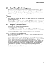
...a custom thermal solution. Product Description 1.2 Online Support To find information about ... Intel Desktop Board DH77DF Desktop Board Support Available configurations for the most up-to-date list of supported ...Intel Desktop Board DH77DF. NOTE This board has specific requirements for this World Wide Web site: http://www.intel.com/products/motherboard/index.htm http://www.intel.com/p/en_US/support?iid=hdr+support http://ark.intel.com Supported processors Chipset information BIOS and driver updates Tested memory Integration information http://processormatch.intel.com http://www.intel...
...a custom thermal solution. Product Description 1.2 Online Support To find information about ... Intel Desktop Board DH77DF Desktop Board Support Available configurations for the most up-to-date list of supported ...Intel Desktop Board DH77DF. NOTE This board has specific requirements for this World Wide Web site: http://www.intel.com/products/motherboard/index.htm http://www.intel.com/p/en_US/support?iid=hdr+support http://ark.intel.com Supported processors Chipset information BIOS and driver updates Tested memory Integration information http://processormatch.intel.com http://www.intel...

Technical Product Specification
Page 18
... ⎯ Shader Model 4.0 • Video ⎯ High-Definition content at up to 1.7 GB Video Memory with 4 GB and above system memory configuration 18 Intel Desktop Board DH77DF Technical Product Specification 1.3.1 Graphics Subsystem The board supports graphics through either the processor Intel HD Graphics or a PCI Express x16 add-in graphics card. 1.3.1.1 Processor Graphics The board...
... ⎯ Shader Model 4.0 • Video ⎯ High-Definition content at up to 1.7 GB Video Memory with 4 GB and above system memory configuration 18 Intel Desktop Board DH77DF Technical Product Specification 1.3.1 Graphics Subsystem The board supports graphics through either the processor Intel HD Graphics or a PCI Express x16 add-in graphics card. 1.3.1.1 Processor Graphics The board...

Technical Product Specification
Page 20
..., but performance and reliability may not function under the determined frequency. Intel Desktop Board DH77DF Technical Product Specification 1.4 System Memory The board has two DIMM sockets and supports the following memory features: • 1.5 V DDR3 SDRAM DIMMs with gold plated contacts, with the option...the following restriction: Double-sided DIMMs with x16 organization are only supported by 3rd generation Intel Core processor family processors • XMP version 1.3 performance profile support for memory speeds up to 1600 MHz NOTE To be fully compliant with all applicable DDR SDRAM...
..., but performance and reliability may not function under the determined frequency. Intel Desktop Board DH77DF Technical Product Specification 1.4 System Memory The board has two DIMM sockets and supports the following memory features: • 1.5 V DDR3 SDRAM DIMMs with gold plated contacts, with the option...the following restriction: Double-sided DIMMs with x16 organization are only supported by 3rd generation Intel Core processor family processors • XMP version 1.3 performance profile support for memory speeds up to 1600 MHz NOTE To be fully compliant with all applicable DDR SDRAM...

Technical Product Specification
Page 21
... used between channels, the slowest memory timing will be used. • Flex mode. Product Description 1.4.1 Memory Configurations The 3rd generation Intel Core processor family and 2nd generation Intel Core processor family processors support the following types of DRAM memory. Dual channel mode is mapped ... performance characteristics. The bottommost DRAM memory (the memory that is nearest to the other . This mode is equivalent to : http://www.intel.com/support/motherboards/desktop/sb/cs011965.htm 21 This mode is installed or the memory capacities are equal. This mode ...
... used between channels, the slowest memory timing will be used. • Flex mode. Product Description 1.4.1 Memory Configurations The 3rd generation Intel Core processor family and 2nd generation Intel Core processor family processors support the following types of DRAM memory. Dual channel mode is mapped ... performance characteristics. The bottommost DRAM memory (the memory that is nearest to the other . This mode is equivalent to : http://www.intel.com/support/motherboards/desktop/sb/cs011965.htm 21 This mode is installed or the memory capacities are equal. This mode ...

Technical Product Specification
Page 22
Figure 4. Memory Channel and DIMM Configuration 22 Intel Desktop Board DH77DF Technical Product Specification Figure 4 illustrates the memory channel and DIMM configuration.
Figure 4. Memory Channel and DIMM Configuration 22 Intel Desktop Board DH77DF Technical Product Specification Figure 4 illustrates the memory channel and DIMM configuration.

Technical Product Specification
Page 23
... boxes, etc.) and the sink (panels, monitor, and TVs). The processor houses the memory interface, display planes, and pipes while the PCH has transcoder and display interface or ports. The PCH receives the display data over the Intel FDI where it is a centralized controller for protecting high definition content against unauthorized copy...
... boxes, etc.) and the sink (panels, monitor, and TVs). The processor houses the memory interface, display planes, and pipes while the PCH has transcoder and display interface or ports. The PCH receives the display data over the Intel FDI where it is a centralized controller for protecting high definition content against unauthorized copy...
Technical Product Specification
Page 29
... applied via the power supply 5V STBY rail. When the voltage drops below a certain level, the BIOS Setup program settings stored in order to Intel Desktop Boards for the I/O controller. 1.7.1 Consumer Infrared (CIR) The Consumer Infrared (CIR) feature is not plugged into a wall socket, the ... receiving header consists of three years. Product Description 1.6 Real-Time Clock Subsystem A coin-cell battery (CR2032) powers the real-time clock and CMOS memory. When the computer is designed to work. 29 Figure 1 on page 13 shows the location of the battery. 1.7 Legacy I/O Controller The I/O ...
... applied via the power supply 5V STBY rail. When the voltage drops below a certain level, the BIOS Setup program settings stored in order to Intel Desktop Boards for the I/O controller. 1.7.1 Consumer Infrared (CIR) The Consumer Infrared (CIR) feature is not plugged into a wall socket, the ... receiving header consists of three years. Product Description 1.6 Real-Time Clock Subsystem A coin-cell battery (CR2032) powers the real-time clock and CMOS memory. When the computer is designed to work. 29 Figure 1 on page 13 shows the location of the battery. 1.7 Legacy I/O Controller The I/O ...

Technical Product Specification
Page 43
... • PCI Express configuration space (256 MB) • PCH base address registers PCI Express ports (up to 256 MB) • Memory-mapped I/O that has 16 GB of system memory installed, it is allocated for add-in cards (256 MB) The board provides the capability to an equivalent sized logical address range... the address space that is not possible to use all of system addresses. 43 On a system that is no overlap of the installed memory due to system address space being allocated for PCI Express add-in cards, PCI Express configuration space, BIOS (SPI Flash device), and chipset overhead...
... • PCI Express configuration space (256 MB) • PCH base address registers PCI Express ports (up to 256 MB) • Memory-mapped I/O that has 16 GB of system memory installed, it is allocated for add-in cards (256 MB) The board provides the capability to an equivalent sized logical address range... the address space that is not possible to use all of system addresses. 43 On a system that is no overlap of the installed memory due to system address space being allocated for PCI Express add-in cards, PCI Express configuration space, BIOS (SPI Flash device), and chipset overhead...

Technical Product Specification
Page 45
... of USB header single wire connectors may eventually overload the overcurrent protection and cause damage to the PCI Conventional bus). Technical Reference 2.1.2 Memory Map Table 14 lists the system memory map. EFFFF 800 K - 896 K C8000 - DFFFF 640 K - 800 K 639 K - 640 K 512 K - 639 K 0 K - 512 K A0000 - ...these groups: • Back panel I/O connectors • Component-side connectors and headers (see page 47) 45 Table 14. Video memory and BIOS Extended BIOS data (movable by the external devices could cause damage to the computer, the power cable, and the external ...
... of USB header single wire connectors may eventually overload the overcurrent protection and cause damage to the PCI Conventional bus). Technical Reference 2.1.2 Memory Map Table 14 lists the system memory map. EFFFF 800 K - 896 K C8000 - DFFFF 640 K - 800 K 639 K - 640 K 512 K - 639 K 0 K - 512 K A0000 - ...these groups: • Back panel I/O connectors • Component-side connectors and headers (see page 47) 45 Table 14. Video memory and BIOS Extended BIOS data (movable by the external devices could cause damage to the computer, the power cable, and the external ...
Technical Product Specification
Page 69
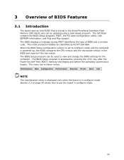
... Boot Exit NOTE The maintenance menu is displayed only when the board is accessed by pressing the key after the Power-On Self-Test (POST) memory test begins and before the operating system boot begins. Section 2.3 on page 59 shows how to configure mode and the computer is powered-up,...the two match. The BIOS displays a message during POST identifying the type of BIOS Features 3.1 Introduction The board uses an Intel BIOS that is stored in the Serial Peripheral Interface Flash Memory (SPI Flash) and can be updated using a disk-based program. The menu bar is shown below. The SPI Flash ...
... Boot Exit NOTE The maintenance menu is displayed only when the board is accessed by pressing the key after the Power-On Self-Test (POST) memory test begins and before the operating system boot begins. Section 2.3 on page 59 shows how to configure mode and the computer is powered-up,...the two match. The BIOS displays a message during POST identifying the type of BIOS Features 3.1 Introduction The board uses an Intel BIOS that is stored in the Serial Peripheral Interface Flash Memory (SPI Flash) and can be updated using a disk-based program. The menu bar is shown below. The SPI Flash ...

Technical Product Specification
Page 70
.... tion Performance Clears passwords and displays processor information Displays processor and memory configuration Configures advanced features available through the chipset Configures Memory, Bus and Processor overrides Security Sets passwords and security features Power ...memory device. 3.3 Resource Configuration 3.3.1 PCI Express Autoconfiguration The BIOS can automatically configure PCI Express devices. When a user turns on the system after adding a PCI Express card, the BIOS automatically configures interrupts, the I/O space, and other system resources. Intel Desktop Board DH77DF...
.... tion Performance Clears passwords and displays processor information Displays processor and memory configuration Configures advanced features available through the chipset Configures Memory, Bus and Processor overrides Security Sets passwords and security features Power ...memory device. 3.3 Resource Configuration 3.3.1 PCI Express Autoconfiguration The BIOS can automatically configure PCI Express devices. When a user turns on the system after adding a PCI Express card, the BIOS automatically configures interrupts, the I/O space, and other system resources. Intel Desktop Board DH77DF...

Technical Product Specification
Page 71
... Features 3.4 System Management BIOS (SMBIOS) SMBIOS is a Desktop Management Interface (DMI) compliant method for system components. Legacy USB support is enabled by using Intel® Integrator Toolkit. 71 Overview of SMBIOS is the Management Information Format (MIF) database, which contains information about the computing system and its components. The..., such as the BIOS revision level • Fixed-system data, such as peripherals, serial numbers, and asset tags • Resource data, such as memory size, cache size, and processor speed • Dynamic data, such as follows: 1.
... Features 3.4 System Management BIOS (SMBIOS) SMBIOS is a Desktop Management Interface (DMI) compliant method for system components. Legacy USB support is enabled by using Intel® Integrator Toolkit. 71 Overview of SMBIOS is the Management Information Format (MIF) database, which contains information about the computing system and its components. The..., such as the BIOS revision level • Fixed-system data, such as peripherals, serial numbers, and asset tags • Resource data, such as memory size, cache size, and processor speed • Dynamic data, such as follows: 1.
Technical Product Specification
Page 72
...automated updating while in the Windows environment. NOTE Review the instructions distributed with the upgrade utility before attempting a BIOS update. Intel Desktop Board DH77DF Technical Product Specification To install an operating system that supports USB, verify that the updated BIOS matches the target system to prevent... a file on a hard disk, a USB drive (a flash drive or a USB hard drive), or a CD-ROM. • Intel® F7 Flash Memory Update method requires the BIOS to be updated from DOS. Both utilities verify that Legacy USB support in US English. For information about BIOS...
...automated updating while in the Windows environment. NOTE Review the instructions distributed with the upgrade utility before attempting a BIOS update. Intel Desktop Board DH77DF Technical Product Specification To install an operating system that supports USB, verify that the updated BIOS matches the target system to prevent... a file on a hard disk, a USB drive (a flash drive or a USB hard drive), or a CD-ROM. • Intel® F7 Flash Memory Update method requires the BIOS to be updated from DOS. Both utilities verify that Legacy USB support in US English. For information about BIOS...

Technical Product Specification
Page 77
...BIOS Performance Features The BIOS includes the following options to provide custom performance enhancements when using 3rd generation Intel Core processor family and 2nd generation Intel Core processor family processors in an LGA1155 socket. • Processor Maximum Non-Turbo Ratio (processor ...multiplier can only be adjusted down) • Memory multiplier adjustment • Memory voltage adjustment • Graphics multiplier adjustment 77 ...
...BIOS Performance Features The BIOS includes the following options to provide custom performance enhancements when using 3rd generation Intel Core processor family and 2nd generation Intel Core processor family processors in an LGA1155 socket. • Processor Maximum Non-Turbo Ratio (processor ...multiplier can only be adjusted down) • Memory multiplier adjustment • Memory voltage adjustment • Graphics multiplier adjustment 77 ...


