

Product Specification
Page 7
...13 1.1.3 Block Diagram 15 1.2 Legacy Considerations 16 1.3 Online Support 16 1.4 Processor 17 1.4.1 PCI Express x16 Graphics 17 1.5 System Memory 18 1.5.1 Memory Configurations 19 1.6 Intel® H67 Express Chipset 21 1.7 Graphics Subsystem 21 1.7.1 Integrated Graphics 21 1.7.2 USB 24 1.8 SATA Interfaces 25 1.9 Real-Time ... Audio Subsystem 27 1.11.1 Audio Subsystem Software 27 1.11.2 Audio Subsystem Components 27 1.12 LAN Subsystem 29 1.12.1 Intel® 82579V Gigabit Ethernet Controller 29 1.12.2 LAN Subsystem Software 30 1.12.3 RJ-45 LAN Connector with Integrated LEDs 30...
...13 1.1.3 Block Diagram 15 1.2 Legacy Considerations 16 1.3 Online Support 16 1.4 Processor 17 1.4.1 PCI Express x16 Graphics 17 1.5 System Memory 18 1.5.1 Memory Configurations 19 1.6 Intel® H67 Express Chipset 21 1.7 Graphics Subsystem 21 1.7.1 Integrated Graphics 21 1.7.2 USB 24 1.8 SATA Interfaces 25 1.9 Real-Time ... Audio Subsystem 27 1.11.1 Audio Subsystem Software 27 1.11.2 Audio Subsystem Components 27 1.12 LAN Subsystem 29 1.12.1 Intel® 82579V Gigabit Ethernet Controller 29 1.12.2 LAN Subsystem Software 30 1.12.3 RJ-45 LAN Connector with Integrated LEDs 30...

Product Specification
Page 8
Intel Desktop Board DH67CF Technical Product Specification 1.14 Power Management 33 1.14.1 ACPI 33 1.14.2 Hardware Support 35 2 Technical Reference 2.1 Memory Resources 41 2.1.1 Addressable Memory 41 2.1.2 Memory Map 43 2.2 Connectors and Headers 43 2.2.1 Back Panel Connectors 44 2.2.2...Considerations 57 2.6 Thermal Considerations 57 2.7 Reliability 60 2.8 Environmental 60 3 Overview of BIOS Features 3.1 Introduction 61 3.2 BIOS Flash Memory Organization 62 3.3 System Management BIOS (SMBIOS 63 3.4 Legacy USB Support 63 3.5 BIOS Updates 64 3.5.1 Language Support 64 3.5.2 Custom...
Intel Desktop Board DH67CF Technical Product Specification 1.14 Power Management 33 1.14.1 ACPI 33 1.14.2 Hardware Support 35 2 Technical Reference 2.1 Memory Resources 41 2.1.1 Addressable Memory 41 2.1.2 Memory Map 43 2.2 Connectors and Headers 43 2.2.1 Back Panel Connectors 44 2.2.2...Considerations 57 2.6 Thermal Considerations 57 2.7 Reliability 60 2.8 Environmental 60 3 Overview of BIOS Features 3.1 Introduction 61 3.2 BIOS Flash Memory Organization 62 3.3 System Management BIOS (SMBIOS 63 3.4 Legacy USB Support 63 3.5 BIOS Updates 64 3.5.1 Language Support 64 3.5.2 Custom...

Product Specification
Page 9
... Information 5.1 Regulatory Compliance 77 5.1.1 Safety Standards 77 5.1.2 European Union Declaration of the Jumper Block 53 14. Back Panel Audio Connectors 28 5. Detailed System Memory Address Map 42 9. Location of Conformity Statement 78 5.1.3 Product Ecology Statements 79 5.1.4 EMC Regulations 81 5.1.5 ENERGY STAR* 5.0, e-Standby, and ErP Compliance ... 6. Major Board Components 13 2. Audio Jack Support 27 7. Thermal Sensors and Fan Headers 32 7. Front Panel Audio Header for Intel HD Audio 47 14. Effects of the Standby Power LED 39 8. Block Diagram 15 3.
... Information 5.1 Regulatory Compliance 77 5.1.1 Safety Standards 77 5.1.2 European Union Declaration of the Jumper Block 53 14. Back Panel Audio Connectors 28 5. Detailed System Memory Address Map 42 9. Location of Conformity Statement 78 5.1.3 Product Ecology Statements 79 5.1.4 EMC Regulations 81 5.1.5 ENERGY STAR* 5.0, e-Standby, and ErP Compliance ... 6. Major Board Components 13 2. Audio Jack Support 27 7. Thermal Sensors and Fan Headers 32 7. Front Panel Audio Header for Intel HD Audio 47 14. Effects of the Standby Power LED 39 8. Block Diagram 15 3.

Product Specification
Page 11
... DDR3 1066 MHz DIMMs • Support for 1 Gb, 2 Gb, and 4 Gb memory technology • Support for up to 16 GB of system memory with two DIMMs using 4 Gb memory technology • Support for non-ECC memory • Support for 1.35 V low voltage JEDEC memory Intel® H67 Express Chipset consisting of the board. 1 Product Description 1.1 Overview...
... DDR3 1066 MHz DIMMs • Support for 1 Gb, 2 Gb, and 4 Gb memory technology • Support for up to 16 GB of system memory with two DIMMs using 4 Gb memory technology • Support for non-ECC memory • Support for 1.35 V low voltage JEDEC memory Intel® H67 Express Chipset consisting of the board. 1 Product Description 1.1 Overview...

Product Specification
Page 16
... processors Chipset information BIOS and driver updates Tested memory Integration information http://processormatch.intel.com http://www.intel.com/products/desktop/chipsets/index.htm http://downloadcenter.intel.com http://www.intel.com/support/motherboards/desktop/sb/CS025414.htm http://www.intel.com/support/go/buildit 16 Intel Desktop Board DH67CF Technical Product Specification 1.2 Legacy Considerations This board differs...
... processors Chipset information BIOS and driver updates Tested memory Integration information http://processormatch.intel.com http://www.intel.com/products/desktop/chipsets/index.htm http://downloadcenter.intel.com http://www.intel.com/support/motherboards/desktop/sb/CS025414.htm http://www.intel.com/support/go/buildit 16 Intel Desktop Board DH67CF Technical Product Specification 1.2 Legacy Considerations This board differs...

Product Specification
Page 18
... the DIMMs may not function under the determined frequency. Tested Memory Refer to accurately configure memory settings for optimum performance. Table 3 lists the supported DIMM configurations. Intel Desktop Board DH67CF Technical Product Specification 1.5 System Memory The board has two DIMM sockets and supports the following memory features: • 1.5 V DDR3 SDRAM DIMMs with gold plated contacts, with...
... the DIMMs may not function under the determined frequency. Tested Memory Refer to accurately configure memory settings for optimum performance. Table 3 lists the supported DIMM configurations. Intel Desktop Board DH67CF Technical Product Specification 1.5 System Memory The board has two DIMM sockets and supports the following memory features: • 1.5 V DDR3 SDRAM DIMMs with gold plated contacts, with...

Product Specification
Page 19
...both DIMM channels are used between channels, the slowest memory timing will be used when only a single DIMM is mapped to dual channel operation; Product Description 1.5.1 Memory Configurations The Intel Core i7, Intel Core i5, and Intel Core i3 processors in multiple zones of dual and single... channel operation across the whole of DRAM memory. If different speed DIMMs are equal. This mode is ...
...both DIMM channels are used between channels, the slowest memory timing will be used when only a single DIMM is mapped to dual channel operation; Product Description 1.5.1 Memory Configurations The Intel Core i7, Intel Core i5, and Intel Core i3 processors in multiple zones of dual and single... channel operation across the whole of DRAM memory. If different speed DIMMs are equal. This mode is ...

Product Specification
Page 20
Figure 3. Memory Channel and DIMM Configuration NOTE The Intel Core i7, Intel Core i5, and Intel Core i3 processors require memory to be populated in the DIMM 1 (Channel A, DIMM 1) socket. 20 Intel Desktop Board DH67CF Technical Product Specification Figure 3 illustrates the memory channel and DIMM configuration.
Figure 3. Memory Channel and DIMM Configuration NOTE The Intel Core i7, Intel Core i5, and Intel Core i3 processors require memory to be populated in the DIMM 1 (Channel A, DIMM 1) socket. 20 Intel Desktop Board DH67CF Technical Product Specification Figure 3 illustrates the memory channel and DIMM configuration.

Product Specification
Page 22
Intel Desktop Board DH67CF Technical Product Specification ⎯ Dynamic Video Memory Technology (DVMT) 5.0 support ⎯ Support of add-in card installed in the PCI Express x16 connector, the DVI port will behave as described in Table...Enabled (Note) 1.7.1.3 Digital Visual Interface (DVI-I) The DVI-I connector status. DVI analog output can also be converted to VGA with 4 GB and above system memory configuration 1.7.1.2 High Definition Multimedia Interface* (HDMI*) The HDMI port supports standard, enhanced, or high definition video, plus multichannel digital audio on the type of ...
Intel Desktop Board DH67CF Technical Product Specification ⎯ Dynamic Video Memory Technology (DVMT) 5.0 support ⎯ Support of add-in card installed in the PCI Express x16 connector, the DVI port will behave as described in Table...Enabled (Note) 1.7.1.3 Digital Visual Interface (DVI-I) The DVI-I connector status. DVI analog output can also be converted to VGA with 4 GB and above system memory configuration 1.7.1.2 High Definition Multimedia Interface* (HDMI*) The HDMI port supports standard, enhanced, or high definition video, plus multichannel digital audio on the type of ...

Product Specification
Page 26
... Setup program provides configuration options for the I/O controller. 1.10.1 Consumer Infrared (CIR) The Consumer Infrared (CIR) feature is accurate to Intel Desktop Boards for example, the date and time) might not be notified during the POST. Figure 1 on page 13 shows the location ...is designed to speak the infrared communication language of other user remotes. Intel Desktop Board DH67CF Technical Product Specification 1.9 Real-Time Clock Subsystem A coin-cell battery (CR2032) powers the real-time clock and CMOS memory. When the computer is plugged in, the standby current from the ...
... Setup program provides configuration options for the I/O controller. 1.10.1 Consumer Infrared (CIR) The Consumer Infrared (CIR) feature is accurate to Intel Desktop Boards for example, the date and time) might not be notified during the POST. Figure 1 on page 13 shows the location ...is designed to speak the infrared communication language of other user remotes. Intel Desktop Board DH67CF Technical Product Specification 1.9 Real-Time Clock Subsystem A coin-cell battery (CR2032) powers the real-time clock and CMOS memory. When the computer is plugged in, the standby current from the ...

Product Specification
Page 41
...DRAM boundary to the 4 GB boundary to an equivalent sized logical address range located just above the top of the installed memory due to use all of DRAM (total system memory). Typically the address space that is allocated for PCI Express add-in cards (256 MB) The board provides the capability... to 256 MB) • Memory-mapped I /O logical address space. These functions include the following: • BIOS/SPI Flash device (16 Mbit) • Local APIC (19 MB) • Direct Media ...
...DRAM boundary to the 4 GB boundary to an equivalent sized logical address range located just above the top of the installed memory due to use all of DRAM (total system memory). Typically the address space that is allocated for PCI Express add-in cards (256 MB) The board provides the capability... to 256 MB) • Memory-mapped I /O logical address space. These functions include the following: • BIOS/SPI Flash device (16 Mbit) • Local APIC (19 MB) • Direct Media ...

Product Specification
Page 43
... to devices inside the computer's chassis, such as fans and internal peripherals. A fault in the load presented by memory manager software) Extended conventional memory Conventional memory 2.2 Connectors and Headers CAUTION Only the following connectors and headers have overcurrent protection: back panel and front panel USB....Size 16382 MB 64 KB 64 KB 96 KB 160 KB 1 KB 127 KB 512 KB Description Extended memory Runtime BIOS Reserved Potential available high DOS memory (open to the computer's chassis. The connectors can be divided into these connectors or headers to power ...
... to devices inside the computer's chassis, such as fans and internal peripherals. A fault in the load presented by memory manager software) Extended conventional memory Conventional memory 2.2 Connectors and Headers CAUTION Only the following connectors and headers have overcurrent protection: back panel and front panel USB....Size 16382 MB 64 KB 64 KB 96 KB 160 KB 1 KB 127 KB 512 KB Description Extended memory Runtime BIOS Reserved Potential available high DOS memory (open to the computer's chassis. The connectors can be divided into these connectors or headers to power ...
Product Specification
Page 61
...LAN EEPROM information, and Plug and Play support. The BIOS displays a message during POST identifying the type of BIOS Features 3.1 Introduction The board uses an Intel BIOS that is stored in configure mode. 61 The menu bar is accessed by pressing the key after the Power-On Self-Test (POST... begins and before the operating system boot begins. Section 2.3 on page 53 shows how to put the board in the Serial Peripheral Interface Flash Memory (SPI Flash) and can be updated using a disk-based program. 3 Overview of BIOS and a revision code. The BIOS Setup program can be used to ...
...LAN EEPROM information, and Plug and Play support. The BIOS displays a message during POST identifying the type of BIOS Features 3.1 Introduction The board uses an Intel BIOS that is stored in configure mode. 61 The menu bar is accessed by pressing the key after the Power-On Self-Test (POST... begins and before the operating system boot begins. Section 2.3 on page 53 shows how to put the board in the Serial Peripheral Interface Flash Memory (SPI Flash) and can be updated using a disk-based program. 3 Overview of BIOS and a revision code. The BIOS Setup program can be used to ...

Product Specification
Page 62
Table 36. BIOS Setup Program Menu Bar Maintenance Main Configura- Table 37. Intel Desktop Board DH67CF Technical Product Specification Table 36 lists the BIOS Setup program menu features. BIOS Setup Program Function Keys ... configuration values for menu screens. tion Performance Clears passwords and displays processor information Displays processor and memory configuration Configures advanced features available through the chipset Configures Memory, Bus and Processor overrides Security Sets passwords and security features Power Configures power management features and ...
Table 36. BIOS Setup Program Menu Bar Maintenance Main Configura- Table 37. Intel Desktop Board DH67CF Technical Product Specification Table 36 lists the BIOS Setup program menu features. BIOS Setup Program Function Keys ... configuration values for menu screens. tion Performance Clears passwords and displays processor information Displays processor and memory configuration Configures advanced features available through the chipset Configures Memory, Bus and Processor overrides Security Sets passwords and security features Power Configures power management features and ...
Product Specification
Page 63
... systems. Using this period if Legacy USB support was set to the computer, legacy support is loading, USB keyboards and mice are recognized by using Intel® Integrator Toolkit. 63 Legacy USB support is used even when the operating system's USB drivers are not recognized during this support, an SMBIOS service...; BIOS data, such as the BIOS revision level • Fixed-system data, such as peripherals, serial numbers, and asset tags • Resource data, such as memory size, cache size, and processor speed • Dynamic data, such as follows: 1. POST begins. 3.
... systems. Using this period if Legacy USB support was set to the computer, legacy support is loading, USB keyboards and mice are recognized by using Intel® Integrator Toolkit. 63 Legacy USB support is used even when the operating system's USB drivers are not recognized during this support, an SMBIOS service...; BIOS data, such as the BIOS revision level • Fixed-system data, such as peripherals, serial numbers, and asset tags • Resource data, such as memory size, cache size, and processor speed • Dynamic data, such as follows: 1. POST begins. 3.

Product Specification
Page 64
Intel Desktop Board DH67CF Technical Product Specification To install an operating system that supports USB, verify that Legacy USB support in the BIOS Setup program is located and perform the update from that the updated BIOS matches the target system to http://support.intel.com/support/...Support The BIOS Setup program and help messages are available on the Intel World Wide Web site: • Intel® Express BIOS Update utility, which requires booting from a file on the Web. • Intel® Flash Memory Update Utility, which enables automated updating while in US English. ...
Intel Desktop Board DH67CF Technical Product Specification To install an operating system that supports USB, verify that Legacy USB support in the BIOS Setup program is located and perform the update from that the updated BIOS matches the target system to http://support.intel.com/support/...Support The BIOS Setup program and help messages are available on the Intel World Wide Web site: • Intel® Express BIOS Update utility, which requires booting from a file on the Web. • Intel® Flash Memory Update Utility, which enables automated updating while in US English. ...
Product Specification
Page 69
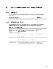
... BIOS is ready to Prompt accept keyboard input BIOS update in progress None Video error On-off (1.0 second each) two times, then 2.5-second pause (off . Memory error On-off (1.0 second each ) for eight beeps, followed by system shut down. 4 Error Messages and Beep Codes 4.1 Speaker The board-mounted speaker provides audible...
... BIOS is ready to Prompt accept keyboard input BIOS update in progress None Video error On-off (1.0 second each) two times, then 2.5-second pause (off . Memory error On-off (1.0 second each ) for eight beeps, followed by system shut down. 4 Error Messages and Beep Codes 4.1 Speaker The board-mounted speaker provides audible...
Product Specification
Page 70
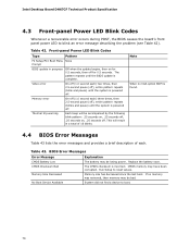
... until the system is powered off for 0.5 seconds, then off . Video error Memory error On-off (1.0 second each) two times, then 2.5-second pause (off . Note When no memory was removed, then memory may be accompanied by the following blink pattern: .25 seconds on, .25 seconds... be losing power. Replace the battery soon. Table 42. This will be bad. Memory Size Decreased Memory size has decreased since the last boot. On-off . Table 43. Intel Desktop Board DH67CF Technical Product Specification 4.3 Front-panel Power LED Blink Codes Whenever a recoverable error occurs ...
... until the system is powered off for 0.5 seconds, then off . Video error Memory error On-off (1.0 second each) two times, then 2.5-second pause (off . Note When no memory was removed, then memory may be accompanied by the following blink pattern: .25 seconds on, .25 seconds... be losing power. Replace the battery soon. Table 42. This will be bad. Memory Size Decreased Memory size has decreased since the last boot. On-off . Table 43. Intel Desktop Board DH67CF Technical Product Specification 4.3 Front-panel Power LED Blink Codes Whenever a recoverable error occurs ...

Product Specification
Page 71
Table 44. Security (SEC) phase PEI phase pre MRC execution MRC memory detection PEI phase post MRC execution Recovery Platform DXE driver CPU Initialization (PEI, DXE, SMM) I /O port 80h. For future use Boot Devices: Includes fixed media ...
Table 44. Security (SEC) phase PEI phase pre MRC execution MRC memory detection PEI phase post MRC execution Recovery Platform DXE driver CPU Initialization (PEI, DXE, SMM) I /O port 80h. For future use Boot Devices: Includes fixed media ...

Product Specification
Page 72
... Exit PEI over-clock programming Memory 0x21 0x23 MRC entry point Reading SPD from memory DIMMs 0x24 Detecting presence of memory DIMMs 0x27 Configuring memory 0x28 Testing memory 0x29 Exit MRC driver PEI after MRC 0x2A Start to Program MTRR Settings 0x2B Done Programming MTRR Settings continued 72 Intel Desktop Board DH67CF Technical Product Specification Table 45...
... Exit PEI over-clock programming Memory 0x21 0x23 MRC entry point Reading SPD from memory DIMMs 0x24 Detecting presence of memory DIMMs 0x27 Configuring memory 0x28 Testing memory 0x29 Exit MRC driver PEI after MRC 0x2A Start to Program MTRR Settings 0x2B Done Programming MTRR Settings continued 72 Intel Desktop Board DH67CF Technical Product Specification Table 45...


