
Product Guide
Page 6
Intel Desktop Board DH61WW Product Guide Connecting to the Internal Headers 43 Front Panel Audio Header 44 S/PDIF Header 44 Chassis Intrusion Header 45 TPM Header 45 Front Panel Header 46 Serial Header 46 Front Panel USB 2.0 Header 47 Connecting to the Audio System 48 Connecting Chassis Fan and Power Supply Cables ... Jumper 51 Clearing Passwords in the BIOS Setup Program 52 Replacing the Battery 53 3 Updating the BIOS Updating the BIOS with the Intel® Express BIOS Update Utility 59 Updating the BIOS Using the F7 Function Key 60 Updating the BIOS with the ISO Image BIOS...
Intel Desktop Board DH61WW Product Guide Connecting to the Internal Headers 43 Front Panel Audio Header 44 S/PDIF Header 44 Chassis Intrusion Header 45 TPM Header 45 Front Panel Header 46 Serial Header 46 Front Panel USB 2.0 Header 47 Connecting to the Audio System 48 Connecting Chassis Fan and Power Supply Cables ... Jumper 51 Clearing Passwords in the BIOS Setup Program 52 Replacing the Battery 53 3 Updating the BIOS Updating the BIOS with the Intel® Express BIOS Update Utility 59 Updating the BIOS Using the F7 Function Key 60 Updating the BIOS with the ISO Image BIOS...

Product Guide
Page 7
... Location of the Chassis Fan Header 49 21. Unlatch the Socket Lever 31 7. Removing a PCI Express x16 Graphics Card 41 17. Intel Desktop Board DH61WW China RoHS Material Self Declaration Table 72 vii Removing the Battery 58 24. Connecting a Serial ATA Cable 42 18. Installing a PCI... Express x16 Graphics Card 40 16. Back Panel Audio Connectors 48 20. Intel Desktop Board DH61WW Components 12 2. Connecting the Processor Fan Heat Sink Power Cable to the Processor Fan Header 35 12. Contents Figures 1....
... Location of the Chassis Fan Header 49 21. Unlatch the Socket Lever 31 7. Removing a PCI Express x16 Graphics Card 41 17. Intel Desktop Board DH61WW China RoHS Material Self Declaration Table 72 vii Removing the Battery 58 24. Connecting a Serial ATA Cable 42 18. Installing a PCI... Express x16 Graphics Card 40 16. Back Panel Audio Connectors 48 20. Intel Desktop Board DH61WW Components 12 2. Connecting the Processor Fan Heat Sink Power Cable to the Processor Fan Header 35 12. Contents Figures 1....

Product Guide
Page 8
... LED Blink Codes 66 15. Feature Summary 9 2. Chassis Intrusion Header Signal Names 45 8. Jumper Settings for Intel HD Audio 44 5. Regulatory Compliance Marks 76 viii Intel Desktop Board DH61WW Product Guide Tables 1. Front Panel Header Signal Names 46 10. LAN Status LEDs States 18 4. TPM Header Signal Names 45 9. BIOS Error Messages 66 16...
... LED Blink Codes 66 15. Feature Summary 9 2. Chassis Intrusion Header Signal Names 45 8. Jumper Settings for Intel HD Audio 44 5. Regulatory Compliance Marks 76 viii Intel Desktop Board DH61WW Product Guide Tables 1. Front Panel Header Signal Names 46 10. LAN Status LEDs States 18 4. TPM Header Signal Names 45 9. BIOS Error Messages 66 16...

Product Guide
Page 9
... Technology • Discrete graphics support for PCI Express* 2.0 x16 add-in graphics cards Intel® High Definition Audio (Intel® HD Audio): • Realtek* ALC892 audio codec • Front panel audio header (Intel HD Audio and AC '97 Audio support) • S/PDIF audio header • One PCI Express 2.0 x16 add-in card connector •... DDR3 1333 MHz and DDR3 1066 MHz DIMMs • Support for 1 Gb, 2 Gb, and 4 Gb memory technology • Support for up to 16 GB of Intel® Desktop Board DH61WW. Table 1 summarizes the major features of the Desktop Board. Table 1.
... Technology • Discrete graphics support for PCI Express* 2.0 x16 add-in graphics cards Intel® High Definition Audio (Intel® HD Audio): • Realtek* ALC892 audio codec • Front panel audio header (Intel HD Audio and AC '97 Audio support) • S/PDIF audio header • One PCI Express 2.0 x16 add-in card connector •... DDR3 1333 MHz and DDR3 1066 MHz DIMMs • Support for 1 Gb, 2 Gb, and 4 Gb memory technology • Support for up to 16 GB of Intel® Desktop Board DH61WW. Table 1 summarizes the major features of the Desktop Board. Table 1.
Product Guide
Page 10
Intel Desktop Board DH61WW Product Guide Table 1. Feature Summary (continued) Peripheral Interfaces LAN Support • Six USB 2.0 ports: ― Four USB 2.0 ports are implemented with stacked back panel connectors ― Two USB 2.0 front panel ports are implemented through a dualport internal header • Four SATA 3 Gb/s ports through the Intel... H61 Express Chipset • One serial port header • One parallel port back panel connector • One PS/2* back panel connector for mouse/keyboard support • Intel® 82579V Gigabit (10/100...
Intel Desktop Board DH61WW Product Guide Table 1. Feature Summary (continued) Peripheral Interfaces LAN Support • Six USB 2.0 ports: ― Four USB 2.0 ports are implemented with stacked back panel connectors ― Two USB 2.0 front panel ports are implemented through a dualport internal header • Four SATA 3 Gb/s ports through the Intel... H61 Express Chipset • One serial port header • One parallel port back panel connector • One PS/2* back panel connector for mouse/keyboard support • Intel® 82579V Gigabit (10/100...

Product Guide
Page 16
... for front panel audio connectors • A signal-to an audio port. The maximum theoretical bandwidth on the interface is 2048 x 1536 (QXGA) at a 75 Hz refresh rate. The maximum supported resolution is 8 GB/s in card connector. Intel Desktop Board DH61WW Product Guide ...Graphics Subsystem The board supports either integrated graphics (Intel Graphics Technology) or PCI Express 2.0 x16 graphics. Integrated Graphics The board supports integrated graphics through...
... for front panel audio connectors • A signal-to an audio port. The maximum theoretical bandwidth on the interface is 2048 x 1536 (QXGA) at a 75 Hz refresh rate. The maximum supported resolution is 8 GB/s in card connector. Intel Desktop Board DH61WW Product Guide ...Graphics Subsystem The board supports either integrated graphics (Intel Graphics Technology) or PCI Express 2.0 x16 graphics. Integrated Graphics The board supports integrated graphics through...
Product Guide
Page 17
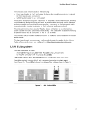
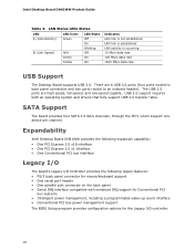
.../. Figure 2. These LEDs indicate the status of 8 Ω at 1 W (rms) or 4 Ω at http://downloadcenter.intel.com/. The back panel audio connectors are available at 1.5 W (rms). LAN Subsystem The LAN subsystem includes: • Intel 82579V Gigabit (10/100/1000 Mb/s) Ethernet LAN controller • RJ-45 LAN connector with integrated status LEDs LAN...
.../. Figure 2. These LEDs indicate the status of 8 Ω at 1 W (rms) or 4 Ω at http://downloadcenter.intel.com/. The back panel audio connectors are available at 1.5 W (rms). LAN Subsystem The LAN subsystem includes: • Intel 82579V Gigabit (10/100/1000 Mb/s) Ethernet LAN controller • RJ-45 LAN connector with integrated status LEDs LAN...
Product Guide
Page 18
The USB 2.0 ports are 6 USB 2.0 ports (four ports routed to back panel connectors and two ports routed to an onboard header). SATA Support The board provides four SATA 3.0 Gb/s channels, through the PCH, which support one device per channel. Expandability Intel Desktop Board DH61WW provides the following expansion capability: • One PCI Express 2.0 x16...
The USB 2.0 ports are 6 USB 2.0 ports (four ports routed to back panel connectors and two ports routed to an onboard header). SATA Support The board provides four SATA 3.0 Gb/s channels, through the PCH, which support one device per channel. Expandability Intel Desktop Board DH61WW provides the following expansion capability: • One PCI Express 2.0 x16...

Product Guide
Page 22
.... 22 Add-in cards that support this feature can be off (the power supply is off and the front panel power LED will appear to be used to wake the computer. Intel Desktop Board DH61WW Product Guide Instantly Available PC Technology CAUTION For Instantly Available PC technology, the 5 V standby line for the power...
.... 22 Add-in cards that support this feature can be off (the power supply is off and the front panel power LED will appear to be used to wake the computer. Intel Desktop Board DH61WW Product Guide Instantly Available PC Technology CAUTION For Instantly Available PC technology, the 5 V standby line for the power...
Product Guide
Page 27
... computer from its power source and from any procedures can damage components. Some circuitry on the board can continue to operate even though the front panel power button is not available, you begin: • Always follow the steps in each procedure in the correct order. • Set up a log to a metal...
... computer from its power source and from any procedures can damage components. Some circuitry on the board can continue to operate even though the front panel power button is not available, you begin: • Always follow the steps in each procedure in the correct order. • Set up a log to a metal...

Product Guide
Page 40
Connect a monitor to the graphics card according to the chassis back panel with a screw (Figure 15, B). 4. Secure the card's metal bracket to the manufacturer's instructions. Intel Desktop Board DH61WW Product Guide Follow these instructions to install a PCI Express x16 graphics card: 1. Installing a PCI Express x16 Graphics Card 40 Figure 15. Observe the precautions in...
Connect a monitor to the graphics card according to the chassis back panel with a screw (Figure 15, B). 4. Secure the card's metal bracket to the manufacturer's instructions. Intel Desktop Board DH61WW Product Guide Follow these instructions to install a PCI Express x16 graphics card: 1. Installing a PCI Express x16 Graphics Card 40 Figure 15. Observe the precautions in...

Product Guide
Page 41
...a pencil or similar tool (Figure 16, B) in "Before You Begin" on page 27. 2. Pull the card straight up to the chassis back panel. 4. Disconnect the monitor cable from the connector (C). 5. Figure 16. Remove the screw (Figure 16, A) that secures the card's metal bracket to ...remove it. This will release the card from the graphics card back panel connector. 3. Observe the precautions in the notch. Installing and Replacing Desktop Board Components Removing a PCI Express x16 Graphics Card Follow these instructions ...
...a pencil or similar tool (Figure 16, B) in "Before You Begin" on page 27. 2. Pull the card straight up to the chassis back panel. 4. Disconnect the monitor cable from the connector (C). 5. Figure 16. Remove the screw (Figure 16, A) that secures the card's metal bracket to ...remove it. This will release the card from the graphics card back panel connector. 3. Observe the precautions in the notch. Installing and Replacing Desktop Board Components Removing a PCI Express x16 Graphics Card Follow these instructions ...

Product Guide
Page 44
Intel Desktop Board DH61WW Product Guide Front Panel Audio Header The front panel audio header shown in Figure 18, A supports both Intel High Definition Audio and AC '97 Audio. Table 4 shows the pin assignments and signal names for HD Audio and Table 5 shows the pin assignments and signal names for the S/PDIF output header. Front Panel...Pin Signal Name 2 AUD_GND 4 PRESENCE# 6 AUD_GND 8 KEY (no pin) 10 SENSE2_RETURN Table 5. Front Panel Audio Header Signal Names for Intel HD Audio Pin Signal Name 1 PORT 1L (Microphone) Pin Signal Name 2 Ground 3 PORT 1R (...
Intel Desktop Board DH61WW Product Guide Front Panel Audio Header The front panel audio header shown in Figure 18, A supports both Intel High Definition Audio and AC '97 Audio. Table 4 shows the pin assignments and signal names for HD Audio and Table 5 shows the pin assignments and signal names for the S/PDIF output header. Front Panel...Pin Signal Name 2 AUD_GND 4 PRESENCE# 6 AUD_GND 8 KEY (no pin) 10 SENSE2_RETURN Table 5. Front Panel Audio Header Signal Names for Intel HD Audio Pin Signal Name 1 PORT 1L (Microphone) Pin Signal Name 2 Ground 3 PORT 1R (...

Product Guide
Page 46
... Send) 10 Key (no pin) 46 Table 9 shows the pin assignments and signal names for the serial header. Table 10. Intel Desktop Board DH61WW Product Guide Front Panel Header Figure 18, E shows the location of the serial header. Serial Header Figure 18, F shows the location of the front... panel header. Front Panel Header Signal Names Pin Description In/Out Pin Description Hard Disk Drive Activity LED Power LED 1 ...
... Send) 10 Key (no pin) 46 Table 9 shows the pin assignments and signal names for the serial header. Table 10. Intel Desktop Board DH61WW Product Guide Front Panel Header Figure 18, E shows the location of the serial header. Serial Header Figure 18, F shows the location of the front... panel header. Front Panel Header Signal Names Pin Description In/Out Pin Description Hard Disk Drive Activity LED Power LED 1 ...

Product Guide
Page 47
Front Panel USB 2.0 Header Signal Names Pin Signal Name 1 Power (+5 V) 3 D- 5 D+ 7 Ground 9 Key Pin Signal Name 2 Power (+5 V) 4 D- 6 D+ 8 Ground 10 No Connection NOTE Computer systems that meets the requirements ... Class B requirements, even if no device or a low-speed USB device is attached to the cable. Table 11. Installing and Replacing Desktop Board Components Front Panel USB 2.0 Header Figure 18, G shows the location of the front panel USB 2.0 header and Table 11 shows the pin assignments and signal names.
Front Panel USB 2.0 Header Signal Names Pin Signal Name 1 Power (+5 V) 3 D- 5 D+ 7 Ground 9 Key Pin Signal Name 2 Power (+5 V) 4 D- 6 D+ 8 Ground 10 No Connection NOTE Computer systems that meets the requirements ... Class B requirements, even if no device or a low-speed USB device is attached to the cable. Table 11. Installing and Replacing Desktop Board Components Front Panel USB 2.0 Header Figure 18, G shows the location of the front panel USB 2.0 header and Table 11 shows the pin assignments and signal names.

Product Guide
Page 48
... Connectors NOTE The back panel line out connector is designed to the Audio System After installing the Realtek audio driver from the Intel® Express Installer DVD-ROM, the multi-channel audio feature can be enabled. Poor audio quality may occur if passive ...(non-amplified) speakers are shown in Figure 19. Figure 19 shows the back panel audio connectors. Intel Desktop Board DH61WW Product Guide Connecting to power either headphones or amplified speakers only. Item Description A Line in B Line out (front speaker/headphones)...
... Connectors NOTE The back panel line out connector is designed to the Audio System After installing the Realtek audio driver from the Intel® Express Installer DVD-ROM, the multi-channel audio feature can be enabled. Poor audio quality may occur if passive ...(non-amplified) speakers are shown in Figure 19. Figure 19 shows the back panel audio connectors. Intel Desktop Board DH61WW Product Guide Connecting to power either headphones or amplified speakers only. Item Description A Line in B Line out (front speaker/headphones)...

Product Guide
Page 65
... On-off (1.0 second each ) for eight beeps followed by system shut down. A Error Messages and Indicators Intel Desktop Board DH61WW reports POST errors in two ways: • By sounding a beep code and blinking the front panel power LED • By displaying an error message on the monitor BIOS Error Codes Whenever a recoverable error...
... On-off (1.0 second each ) for eight beeps followed by system shut down. A Error Messages and Indicators Intel Desktop Board DH61WW reports POST errors in two ways: • By sounding a beep code and blinking the front panel power LED • By displaying an error message on the monitor BIOS Error Codes Whenever a recoverable error...

Product Guide
Page 66
... error Thermal trip warning Pattern None Note Off when the update begins, then on , .25 seconds off . Intel Desktop Board DH61WW Product Guide Table 14. System did not find a device to reset values. Front-panel Power LED Blink Codes Type F2 Setup/F10 Boot Menu Prompt BIOS update in progress Video error (no...
... error Thermal trip warning Pattern None Note Off when the update begins, then on , .25 seconds off . Intel Desktop Board DH61WW Product Guide Table 14. System did not find a device to reset values. Front-panel Power LED Blink Codes Type F2 Setup/F10 Boot Menu Prompt BIOS update in progress Video error (no...

DH61WW Technical Product Specification
Page 8
Intel Desktop Board DH61WW Technical Product Specification 1.16 Power Management 31 1.16.1 ACPI 31 1.16.2 Hardware Support 34 2 Technical Reference 2.1 Memory Resources 38 2.1.1 Addressable Memory 38 2.1.2 Memory Map 40 2.2 Connectors and Headers 40 2.2.1 Back Panel Connectors 41 2.2.2 Component-side Connectors and Headers... the Default Boot Device During POST 64 4 Error Messages and Beep Codes 4.1 Speaker 65 4.2 BIOS Beep Codes 65 4.3 Front-panel Power LED Blink Codes 66 4.4 BIOS Error Messages 66 4.5 Port 80h POST Codes 67 5 Regulatory Compliance and Battery Disposal Information...
Intel Desktop Board DH61WW Technical Product Specification 1.16 Power Management 31 1.16.1 ACPI 31 1.16.2 Hardware Support 34 2 Technical Reference 2.1 Memory Resources 38 2.1.1 Addressable Memory 38 2.1.2 Memory Map 40 2.2 Connectors and Headers 40 2.2.1 Back Panel Connectors 41 2.2.2 Component-side Connectors and Headers... the Default Boot Device During POST 64 4 Error Messages and Beep Codes 4.1 Speaker 65 4.2 BIOS Beep Codes 65 4.3 Front-panel Power LED Blink Codes 66 4.4 BIOS Error Messages 66 4.5 Port 80h POST Codes 67 5 Regulatory Compliance and Battery Disposal Information...

DH61WW Technical Product Specification
Page 9
... Audio 45 16. LAN Connector LED Locations 27 6. Board Dimensions 53 15. Wake-up Devices and Events 33 9. Front Panel Audio Header for Intel HD Audio 45 15. Detailed System Memory Address Map 39 9. Back Panel Connectors 41 10. Feature Summary 11 2. LAN Connector LED States 27 6. Serial Port Header 44 13. Front...
... Audio 45 16. LAN Connector LED Locations 27 6. Board Dimensions 53 15. Wake-up Devices and Events 33 9. Front Panel Audio Header for Intel HD Audio 45 15. Detailed System Memory Address Map 39 9. Back Panel Connectors 41 10. Feature Summary 11 2. LAN Connector LED States 27 6. Serial Port Header 44 13. Front...


