
Technical Product Specification
Page 2
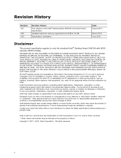
... Date August 2011 March 2012 June 2012 Disclaimer This product specification applies to only the standard Intel® Desktop Board DH61SA with BIOS identifier BEH6110H.86A. Revision History Revision -001 -002 -003 Revision History First release of the Intel® Desktop Board DH61SA Technical Product Specification Updated maximum memory supported from future changes to them...
... Date August 2011 March 2012 June 2012 Disclaimer This product specification applies to only the standard Intel® Desktop Board DH61SA with BIOS identifier BEH6110H.86A. Revision History Revision -001 -002 -003 Revision History First release of the Intel® Desktop Board DH61SA Technical Product Specification Updated maximum memory supported from future changes to them...
Technical Product Specification
Page 3
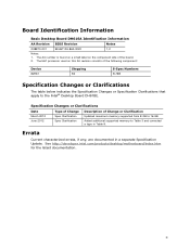
Board Identification Information Basic Desktop Board DH61SA Identification Information AA Revision BIOS Revision Notes G38870-201 BEH6110H.86A.0020 1,2 Notes: 1. Errata Current characterized errata, if any, are documented in Table 9. iii See http://developer.intel.com/products/desktop/motherboard/index.htm for the latest documentation. Specification Changes or Clarifications Date Type ...March 2012 June 2012 Spec Clarification Spec Clarification Updated maximum memory supported from 8 GB to 16 GB Added additional supported memory to the Intel® Desktop Board DH61BE.
Board Identification Information Basic Desktop Board DH61SA Identification Information AA Revision BIOS Revision Notes G38870-201 BEH6110H.86A.0020 1,2 Notes: 1. Errata Current characterized errata, if any, are documented in Table 9. iii See http://developer.intel.com/products/desktop/motherboard/index.htm for the latest documentation. Specification Changes or Clarifications Date Type ...March 2012 June 2012 Spec Clarification Spec Clarification Updated maximum memory supported from 8 GB to 16 GB Added additional supported memory to the Intel® Desktop Board DH61BE.
Technical Product Specification
Page 5
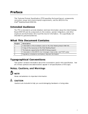
... and abbreviations appear in all specifications of the BIOS error messages, beep codes, and POST codes Regulatory compliance and battery disposal information Typographical Conventions This section contains information about the Intel Desktop Board DH61SA and its components to the vendors, system integrators... intended to provide detailed, technical information about the conventions used on the Intel Desktop Board DH61SA A map of the resources of the Intel Desktop Board The features supported by the BIOS Setup program A description of this type. Intended Audience The TPS is specifically...
... and abbreviations appear in all specifications of the BIOS error messages, beep codes, and POST codes Regulatory compliance and battery disposal information Typographical Conventions This section contains information about the Intel Desktop Board DH61SA and its components to the vendors, system integrators... intended to provide detailed, technical information about the conventions used on the Intel Desktop Board DH61SA A map of the resources of the Intel Desktop Board The features supported by the BIOS Setup program A description of this type. Intended Audience The TPS is specifically...

Technical Product Specification
Page 8
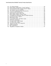
Intel Desktop Board DH61SA Technical Product Specification 2 Technical Reference 2.1 Memory Resources 37 2.1.1 Addressable Memory 37 2.1.2 Memory Map 39 2.2 Connectors and Headers 39 2.2.1 Back Panel Connectors 40 2.2.2 Component-side Connectors and Headers 41 2.3 BIOS Configuration Jumper Block 50 2.4 Mechanical Considerations 52 ...Default Boot Device During POST 64 4 Error Messages and Beep Codes 4.1 Speaker 65 4.2 BIOS Beep Codes 65 4.3 Front-panel Power LED Blink Codes 66 4.4 BIOS Error Messages 66 4.5 Port 80h POST Codes 67 5 Regulatory Compliance and Battery Disposal ...
Intel Desktop Board DH61SA Technical Product Specification 2 Technical Reference 2.1 Memory Resources 37 2.1.1 Addressable Memory 37 2.1.2 Memory Map 39 2.2 Connectors and Headers 39 2.2.1 Back Panel Connectors 40 2.2.2 Component-side Connectors and Headers 41 2.3 BIOS Configuration Jumper Block 50 2.4 Mechanical Considerations 52 ...Default Boot Device During POST 64 4 Error Messages and Beep Codes 4.1 Speaker 65 4.2 BIOS Beep Codes 65 4.3 Front-panel Power LED Blink Codes 66 4.4 BIOS Error Messages 66 4.5 Port 80h POST Codes 67 5 Regulatory Compliance and Battery Disposal ...
Technical Product Specification
Page 10
... Port 80h POST Sequence 72 40. LPC Debug Header 49 25. BIOS Setup Configuration Jumper Settings 51 26. BIOS Setup Program Function Keys 60 32. BIOS Beep Codes 65 35. BIOS Setup Program Menu Bar 60 31. Regulatory Compliance Marks 81 x Intel Desktop Board DH61SA Technical Product Specification 24. Boot Device Menu Options 64 34. Recommended...
... Port 80h POST Sequence 72 40. LPC Debug Header 49 25. BIOS Setup Configuration Jumper Settings 51 26. BIOS Setup Program Function Keys 60 32. BIOS Beep Codes 65 35. BIOS Setup Program Menu Bar 60 31. Regulatory Compliance Marks 81 x Intel Desktop Board DH61SA Technical Product Specification 24. Boot Device Menu Options 64 34. Recommended...

Technical Product Specification
Page 12
...Intel Desktop Board DH61SA Technical Product Specification Table 1. Feature Summary (continued) Peripheral Interfaces • Six USB ports: ― Four USB 2.0 ports are implemented with stacked back panel connectors ― Two USB 2.0 front panel ports are implemented through one dual-port internal header • Two SATA interfaces through the Intel.../mouse port on back panel Legacy I/O Control BIOS • Nuvoton* W83677HG-i Super I/O controller for hardware management and serial port, parallel port, and PS/2 support • Intel® BIOS resident in the SPI Flash device • ...
...Intel Desktop Board DH61SA Technical Product Specification Table 1. Feature Summary (continued) Peripheral Interfaces • Six USB ports: ― Four USB 2.0 ports are implemented with stacked back panel connectors ― Two USB 2.0 front panel ports are implemented through one dual-port internal header • Two SATA interfaces through the Intel.../mouse port on back panel Legacy I/O Control BIOS • Nuvoton* W83677HG-i Super I/O controller for hardware management and serial port, parallel port, and PS/2 support • Intel® BIOS resident in the SPI Flash device • ...
Technical Product Specification
Page 16
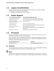
...intel.com Supported processors Chipset information BIOS and driver updates Tested memory Integration information http://processormatch.intel.com http://www.intel.com/products/desktop/chipsets/index.htm http://downloadcenter.intel.com http://www.intel.com/support/motherboards/desktop/sb/CS025414.htm http://www.intel...has specific requirements for the Intel Desktop Board DH61SA Visit this board. 16 Supported processors Refer to support the Intel Core i7, Intel Core i5, Intel Core i3, and Intel Pentium processors in the future. Intel Desktop Board DH61SA Desktop Board Support Available ...
...intel.com Supported processors Chipset information BIOS and driver updates Tested memory Integration information http://processormatch.intel.com http://www.intel.com/products/desktop/chipsets/index.htm http://downloadcenter.intel.com http://www.intel.com/support/motherboards/desktop/sb/CS025414.htm http://www.intel...has specific requirements for the Intel Desktop Board DH61SA Visit this board. 16 Supported processors Refer to support the Intel Core i7, Intel Core i5, Intel Core i3, and Intel Pentium processors in the future. Intel Desktop Board DH61SA Desktop Board Support Available ...
Technical Product Specification
Page 17
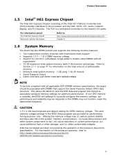
...memory settings for optimum performance. This allows the BIOS to read the SPD data and program the chipset to http://www.intel.com/support/processors/sb/CS020033.htm?wapkw=(processor+warranty). 17 CAUTION 1.5 V is installed, the BIOS will attempt to fail; (iii) cause ... voltage settings in the BIOS Setup program are provided for performance tuning purposes only. Product Description 1.5 Intel® H61 Express Chipset The Intel H61 Express Chipset consisting of the Intel H61 Platform Controller Hub (PCH) provides interfaces to http://www.intel.com/products/desktop/chipsets/...
...memory settings for optimum performance. This allows the BIOS to read the SPD data and program the chipset to http://www.intel.com/support/processors/sb/CS020033.htm?wapkw=(processor+warranty). 17 CAUTION 1.5 V is installed, the BIOS will attempt to fail; (iii) cause ... voltage settings in the BIOS Setup program are provided for performance tuning purposes only. Product Description 1.5 Intel® H61 Express Chipset The Intel H61 Express Chipset consisting of the Intel H61 Platform Controller Hub (PCH) provides interfaces to http://www.intel.com/products/desktop/chipsets/...

Technical Product Specification
Page 21
... connector. The underlying SATA functionality is implemented as a 10-pin header on the back panel • Serial IRQ interface compatible with BIOS support. In Native mode, standard PCI Conventional bus resource steering is the preferred mode for PCI Conventional bus systems • Intelligent power...mode is used. The serial port supports data transfers at speeds up event interface • Conventional PCI bus power management support The BIOS Setup program provides configuration options for the Legacy I/O controller. 1.10.1 Serial Port The serial port is transparent to 115.2 kbits/s ...
... connector. The underlying SATA functionality is implemented as a 10-pin header on the back panel • Serial IRQ interface compatible with BIOS support. In Native mode, standard PCI Conventional bus resource steering is the preferred mode for PCI Conventional bus systems • Intelligent power...mode is used. The serial port supports data transfers at speeds up event interface • Conventional PCI bus power management support The BIOS Setup program provides configuration options for the Legacy I/O controller. 1.10.1 Serial Port The serial port is transparent to 115.2 kbits/s ...

Technical Product Specification
Page 27
... and AC power fail, date and time values will be reset and the user will be accurate. When the voltage drops below a certain level, the BIOS Setup program settings stored in , the standby current from the power supply extends the life of the battery. Figure 1 on page 13 shows the location...
... and AC power fail, date and time values will be reset and the user will be accurate. When the voltage drops below a certain level, the BIOS Setup program settings stored in , the standby current from the power supply extends the life of the battery. Figure 1 on page 13 shows the location...
Technical Product Specification
Page 29
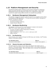
...1.15.2.2 Chassis Intrusion and Detection The board supports a chassis security feature that attaches to be observed through the BIOS setup user interface, Intel® Desktop Utilities or third-party software. The board has several functions designed to manage the system and lower... about The functions of the fan headers Refer to Figure 10, page 41 29 Product Description 1.15 Platform Management and Security Intel DH61SA Desktop Board integrates several hardware management features, including the following : • Processor and system ambient temperature monitoring • Chassis...
...1.15.2.2 Chassis Intrusion and Detection The board supports a chassis security feature that attaches to be observed through the BIOS setup user interface, Intel® Desktop Utilities or third-party software. The board has several functions designed to manage the system and lower... about The functions of the fan headers Refer to Figure 10, page 41 29 Product Description 1.15 Platform Management and Security Intel DH61SA Desktop Board integrates several hardware management features, including the following : • Processor and system ambient temperature monitoring • Chassis...

Technical Product Specification
Page 33
When resuming from an AC power failure, the computer returns to the power state it was in the BIOS Setup program's Boot menu. When an ACPI-enabled system receives the correct command, the power supply removes all non-standby voltages. NOTE The use of ...
When resuming from an AC power failure, the computer returns to the power state it was in the BIOS Setup program's Boot menu. When an ACPI-enabled system receives the correct command, the power supply removes all non-standby voltages. NOTE The use of ...
Technical Product Specification
Page 35
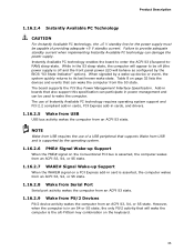
... of providing adequate +5 V standby current. The use of a USB peripheral that can damage the power supply. NOTE Wake from USB and is supported by the BIOS "S3 State Indicator" option).
... of providing adequate +5 V standby current. The use of a USB peripheral that can damage the power supply. NOTE Wake from USB and is supported by the BIOS "S3 State Indicator" option).

Technical Product Specification
Page 37
...of usable DRAM boundary to the 4 GB boundary to 256 MB) • Memory-mapped I /O logical address space. These functions include the following: • BIOS/SPI Flash device (32 Mbit) • Local APIC (19 MB) • Direct Media Interface (40 MB) • PCI Express configuration space (256 MB)...installed system memory can be used when there is dynamically allocated for Conventional PCI and PCI Express add-in cards, PCI Express configuration space, BIOS (SPI Flash device), and chipset overhead resides above the 4 GB boundary. On a system that is not possible to reclaim the physical ...
...of usable DRAM boundary to the 4 GB boundary to 256 MB) • Memory-mapped I /O logical address space. These functions include the following: • BIOS/SPI Flash device (32 Mbit) • Local APIC (19 MB) • Direct Media Interface (40 MB) • PCI Express configuration space (256 MB)...installed system memory can be used when there is dynamically allocated for Conventional PCI and PCI Express add-in cards, PCI Express configuration space, BIOS (SPI Flash device), and chipset overhead resides above the 4 GB boundary. On a system that is not possible to reclaim the physical ...

Technical Product Specification
Page 39
... Memory Map Table 9 lists the system memory map. DFFFF 640 K - 800 K 639 K - 640 K 512 K - 639 K 0 K - 512 K A0000 - Video memory and BIOS Extended BIOS data (movable by the external devices could cause damage to devices inside the computer's chassis, such as fans and internal peripherals. A fault in the load... 00000 - 7FFFF Size 16382 MB 64 KB 64 KB 96 KB 160 KB 1 KB 127 KB 512 KB Description Extended memory Runtime BIOS Reserved Potential available high DOS memory (open to the board. The other internal connectors and headers are not overcurrent protected and should connect ...
... Memory Map Table 9 lists the system memory map. DFFFF 640 K - 800 K 639 K - 640 K 512 K - 639 K 0 K - 512 K A0000 - Video memory and BIOS Extended BIOS data (movable by the external devices could cause damage to devices inside the computer's chassis, such as fans and internal peripherals. A fault in the load... 00000 - 7FFFF Size 16382 MB 64 KB 64 KB 96 KB 160 KB 1 KB 127 KB 512 KB Description Extended memory Runtime BIOS Reserved Potential available high DOS memory (open to the board. The other internal connectors and headers are not overcurrent protected and should connect ...

Technical Product Specification
Page 48
...-color LED. States for a One-Color Power LED LED State Off Steady Lit Blink Description Power off signal. 48 More options are available through BIOS setup. Intel Desktop Board DH61SA Technical Product Specification 2.2.2.4.2 Reset Switch Header Pins 5 and 7 can be connected to a momentary single pole, single throw (SPST) type switch that is due...
...-color LED. States for a One-Color Power LED LED State Off Steady Lit Blink Description Power off signal. 48 More options are available through BIOS setup. Intel Desktop Board DH61SA Technical Product Specification 2.2.2.4.2 Reset Switch Header Pins 5 and 7 can be connected to a momentary single pole, single throw (SPST) type switch that is due...
Technical Product Specification
Page 49
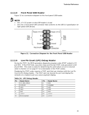
... an error occurred (refer to Section 4.5 on page 67 for the Front Panel USB Header 2.2.2.6 Low Pin Count (LPC) Debug Header During the POST, the BIOS generates diagnostic progress codes (POST codes) to the USB 2.0 specification for the front panel USB header. The POST card can decode the port and display...
... an error occurred (refer to Section 4.5 on page 67 for the Front Panel USB Header 2.2.2.6 Low Pin Count (LPC) Debug Header During the POST, the BIOS generates diagnostic progress codes (POST codes) to the USB 2.0 specification for the front panel USB header. The POST card can decode the port and display...

Technical Product Specification
Page 50
Otherwise, the board could be damaged. Location of the jumper block. The 3-pin jumper block determines the BIOS Setup program's mode. Figure 13 shows the location of the Jumper Block 50 Figure 13. Table 25 describes the jumper settings for the three modes: normal, configure, and recovery. Intel Desktop Board DH61SA Technical Product Specification 2.3 BIOS Configuration Jumper Block CAUTION Do not move the jumper with the power on. Always turn off the power and unplug the power cord from the computer before changing a jumper setting.
Otherwise, the board could be damaged. Location of the jumper block. The 3-pin jumper block determines the BIOS Setup program's mode. Figure 13 shows the location of the Jumper Block 50 Figure 13. Table 25 describes the jumper settings for the three modes: normal, configure, and recovery. Intel Desktop Board DH61SA Technical Product Specification 2.3 BIOS Configuration Jumper Block CAUTION Do not move the jumper with the power on. Always turn off the power and unplug the power cord from the computer before changing a jumper setting.

Technical Product Specification
Page 51
... their default values. Press F9 (restore defaults) while in Configure mode to restore the BIOS/CMOS settings to recover the BIOS configuration. Technical Reference Table 25. BIOS Setup Configuration Jumper Settings Function/Mode Normal Configure Jumper Setting 1-2 2-3 Configuration The BIOS uses current configuration information and passwords for booting. After the POST runs, Setup runs...
... their default values. Press F9 (restore defaults) while in Configure mode to restore the BIOS/CMOS settings to recover the BIOS configuration. Technical Reference Table 25. BIOS Setup Configuration Jumper Settings Function/Mode Normal Configure Jumper Setting 1-2 2-3 Configuration The BIOS uses current configuration information and passwords for booting. After the POST runs, Setup runs...
Technical Product Specification
Page 59
...2.3 on page 50 shows how to view and change the BIOS settings for the computer. The SPI Flash contains the BIOS Setup program, POST, LAN EEPROM information, Plug and Play support, and other firmware. The BIOS Setup program is shown below. The initial production BIOSs are ...Test (POST) memory test begins and before the operating system boot begins. The BIOS displays a message during POST identifying the type of BIOS and a revision code. 3 Overview of BIOS Features 3.1 Introduction The board uses an Intel BIOS that is stored in a 32 Mbit (8.192 KB) Serial Peripheral Interface Flash...
...2.3 on page 50 shows how to view and change the BIOS settings for the computer. The SPI Flash contains the BIOS Setup program, POST, LAN EEPROM information, Plug and Play support, and other firmware. The BIOS Setup program is shown below. The initial production BIOSs are ...Test (POST) memory test begins and before the operating system boot begins. The BIOS displays a message during POST identifying the type of BIOS and a revision code. 3 Overview of BIOS Features 3.1 Introduction The board uses an Intel BIOS that is stored in a 32 Mbit (8.192 KB) Serial Peripheral Interface Flash...


