
Product Specification
Page 6
Intel Desktop Board DG965RY Technical Product Specification 2.6 DMA Channels 47 2.7 PCI Interrupt Routing Map 47 2.8 Connectors and Headers 48 2.8.1 Back Panel Connectors 49 2.8.2 Component-side Connectors and Headers 50 2.9 Jumper Block 58 2.10 Mechanical Considerations 59 2.10.1 Form Factor 59 2.10.2 I/O Shield 60 2.11 Electrical Considerations ...
Intel Desktop Board DG965RY Technical Product Specification 2.6 DMA Channels 47 2.7 PCI Interrupt Routing Map 47 2.8 Connectors and Headers 48 2.8.1 Back Panel Connectors 49 2.8.2 Component-side Connectors and Headers 50 2.9 Jumper Block 58 2.10 Mechanical Considerations 59 2.10.1 Form Factor 59 2.10.2 I/O Shield 60 2.11 Electrical Considerations ...

Product Specification
Page 7
... vii Major Board Components 12 2. LAN Connector LED Locations 32 12. Component-side Connectors and Headers 50 17. Connection Diagram for Front Panel USB Headers 57 19. Feature Summary 10 2. LAN Connector LED States 32 7. Wake-up Devices and Events 37 10. Dual Channel... (Interleaved) Mode Configuration with One DIMM .......... 21 8. Front/Back Panel Audio Connector Options 30 11. Location of the Standby Power Indicator LED 40 14. Board Components Shown in Figure 1 13 3. Single Channel (...
... vii Major Board Components 12 2. LAN Connector LED Locations 32 12. Component-side Connectors and Headers 50 17. Connection Diagram for Front Panel USB Headers 57 19. Feature Summary 10 2. LAN Connector LED States 32 7. Wake-up Devices and Events 37 10. Dual Channel... (Interleaved) Mode Configuration with One DIMM .......... 21 8. Front/Back Panel Audio Connector Options 30 11. Location of the Standby Power Indicator LED 40 14. Board Components Shown in Figure 1 13 3. Single Channel (...
Product Specification
Page 8
... Space Map 45 14. HD Audio Link Header 52 19. States for BIOS Recovery 71 38. DC Loading Characteristics 61 32. Desktop Board DG965RY Environmental Specifications 65 35. BIOS Setup Program Function Keys 68 37. Acceptable Drives/Media Types for a One-Color Power LED 56 29. BIOS... Error Messages 75 42. Port 80h POST Code Ranges 76 43. Intel Desktop Board DG965RY Technical Product Specification 11. Interrupts 46 15. PCI Interrupt Routing Map 48 17. Front Panel Audio Header 52 20. Serial Port Header 52 22. Main Power Connector 54 27. Boot...
... Space Map 45 14. HD Audio Link Header 52 19. States for BIOS Recovery 71 38. DC Loading Characteristics 61 32. Desktop Board DG965RY Environmental Specifications 65 35. BIOS Setup Program Function Keys 68 37. Acceptable Drives/Media Types for a One-Color Power LED 56 29. BIOS... Error Messages 75 42. Port 80h POST Code Ranges 76 43. Intel Desktop Board DG965RY Technical Product Specification 11. Interrupts 46 15. PCI Interrupt Routing Map 48 17. Front Panel Audio Header 52 20. Serial Port Header 52 22. Main Power Connector 54 27. Boot...
Product Specification
Page 10
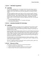
...8226; Support for PCI Express* Revision 1.0a • Suspend to 4 GB of system memory using DDR2 800 DIMMs Intel® G965 Express Chipset, consisting of the Desktop Board DG965RY. Intel Desktop Board DG965RY Technical Product Specification 1.1 Overview 1.1.1 Feature Summary Table 1 summarizes the major features of : •..., and PS/2* ports Support for USB 2.0 devices • 10 USB ports • Two IEEE-1394a interfaces: one back panel connector and one front-panel header • Four Serial ATA IDE interfaces • One Parallel ATA IDE interface with a 533 MHz system bus •...
...8226; Support for PCI Express* Revision 1.0a • Suspend to 4 GB of system memory using DDR2 800 DIMMs Intel® G965 Express Chipset, consisting of the Desktop Board DG965RY. Intel Desktop Board DG965RY Technical Product Specification 1.1 Overview 1.1.1 Feature Summary Table 1 summarizes the major features of : •..., and PS/2* ports Support for USB 2.0 devices • 10 USB ports • Two IEEE-1394a interfaces: one back panel connector and one front-panel header • Four Serial ATA IDE interfaces • One Parallel ATA IDE interface with a 533 MHz system bus •...

Product Specification
Page 13
... add-in card connector H PCI Express x1 connector I PCI Express x16 connector J Back panel connectors K Processor core power connector L Rear chassis fan connector M LGA775 processor socket N Intel 82G965 GMCH O Processor fan header P DIMM Channel A sockets Q Serial port header R...connector U Battery V Front chassis fan header W Chassis intrusion header X Intel 82801HB I/O Controller Hub (ICH8) Y BIOS Setup configuration jumper block Z Auxiliary front panel power LED header AA Front panel header BB Serial ATA connectors [4] CC Speaker DD Parallel ATE IDE ...
... add-in card connector H PCI Express x1 connector I PCI Express x16 connector J Back panel connectors K Processor core power connector L Rear chassis fan connector M LGA775 processor socket N Intel 82G965 GMCH O Processor fan header P DIMM Channel A sockets Q Serial port header R...connector U Battery V Front chassis fan header W Chassis intrusion header X Intel 82801HB I/O Controller Hub (ICH8) Y BIOS Setup configuration jumper block Z Auxiliary front panel power LED header AA Front panel header BB Serial ATA connectors [4] CC Speaker DD Parallel ATE IDE ...

Product Specification
Page 14
Intel Desktop Board DG965RY Technical Product Specification 1.1.3 Block Diagram Figure 2 is a block diagram of the major functional areas. PCI Express x1 Interface PCI Express x1 Slot 1 PCI Express x1 ... ATA IDE Controller System Bus (1066/800/533 MHz) PCI Express x16 Connector Intel G965 Express Chipset PCI Express x16 Interface Display Interface Intel 82G965 Graphics and Memory Controller Hub (GMCH) Gigabit Ethernet Controller LAN Connector USB Back Panel/Front Panel USB Ports Legacy I/O Controller Serial Port Parallel Port PS/2 Mouse PS/2 Keyboard LPC...
Intel Desktop Board DG965RY Technical Product Specification 1.1.3 Block Diagram Figure 2 is a block diagram of the major functional areas. PCI Express x1 Interface PCI Express x1 Slot 1 PCI Express x1 ... ATA IDE Controller System Bus (1066/800/533 MHz) PCI Express x16 Connector Intel G965 Express Chipset PCI Express x16 Interface Display Interface Intel 82G965 Graphics and Memory Controller Hub (GMCH) Gigabit Ethernet Controller LAN Connector USB Back Panel/Front Panel USB Ports Legacy I/O Controller Serial Port Parallel Port PS/2 Mouse PS/2 Keyboard LPC...

Product Specification
Page 24
Intel Desktop Board DG965RY Technical Product Specification • 3D Graphics Rendering enhancements ⎯ 1.3 dual texture GigaPixel/sec fill rate ⎯ 16 and 32 bit color ⎯...Advanced Digital Display 2 card or Media Expansion Card (ADD2/MEC), support for TV-out/TV-in and DVI digital display connections ⎯ Supports flat panels up to 2048 x 1536 at 75 Hz (when in dual-channel mode) or digital CRT/HDTV at 1920 x 1080 at 85 Hz (with... 270 MHz pixel clocks using an ADD2/MEC card • Dynamic Video Memory Technology (DVMT) support up to 256 MB • Intel® Zoom Utility 24
Intel Desktop Board DG965RY Technical Product Specification • 3D Graphics Rendering enhancements ⎯ 1.3 dual texture GigaPixel/sec fill rate ⎯ 16 and 32 bit color ⎯...Advanced Digital Display 2 card or Media Expansion Card (ADD2/MEC), support for TV-out/TV-in and DVI digital display connections ⎯ Supports flat panels up to 2048 x 1536 at 75 Hz (when in dual-channel mode) or digital CRT/HDTV at 1920 x 1080 at 85 Hz (with... 270 MHz pixel clocks using an ADD2/MEC card • Dynamic Video Memory Technology (DVMT) support up to 256 MB • Intel® Zoom Utility 24

Product Specification
Page 26
.../slave configuration and two devices per channel. In legacy mode, standard IDE I/O and IRQ resources are routed to two separate front panel USB headers NOTE Computer systems that meets the requirements for configurations using the Windows* XP and Windows 2000 operating systems. NOTE Many..., supports UHCI and EHCI, and uses UHCIand EHCI-compatible drivers. For information about The location of four Serial ATA devices. Intel Desktop Board DG965RY Technical Product Specification 1.5.2 USB The board supports up to the cable. The ICH8 provides the USB controller for a maximum of...
.../slave configuration and two devices per channel. In legacy mode, standard IDE I/O and IRQ resources are routed to two separate front panel USB headers NOTE Computer systems that meets the requirements for configurations using the Windows* XP and Windows 2000 operating systems. NOTE Many..., supports UHCI and EHCI, and uses UHCIand EHCI-compatible drivers. For information about The location of four Serial ATA devices. Intel Desktop Board DG965RY Technical Product Specification 1.5.2 USB The board supports up to the cable. The ICH8 provides the USB controller for a maximum of...

Product Specification
Page 28
... to Figure 15, page 49 1.6.3 Diskette Drive Controller The I/O controller supports one serial port header located on the back panel. For information about The location of the board. Use the BIOS Setup program to the computer should be turned off before... MB or 2.88 MB diskette drive • Intelligent power management, including a programmable wake-up to configure the diskette drive interface. Intel Desktop Board DG965RY Technical Product Specification 1.6 Legacy I/O Controller The I/O controller provides the following features: • One serial port • One parallel port...
... to Figure 15, page 49 1.6.3 Diskette Drive Controller The I/O controller supports one serial port header located on the back panel. For information about The location of the board. Use the BIOS Setup program to the computer should be turned off before... MB or 2.88 MB diskette drive • Intelligent power management, including a programmable wake-up to configure the diskette drive interface. Intel Desktop Board DG965RY Technical Product Specification 1.6 Legacy I/O Controller The I/O controller provides the following features: • One serial port • One parallel port...

Product Specification
Page 29
...Table 5 lists the supported retasking functions of the following: • Intel 82801HB ICH8 • Sigmatel STAC9227 audio codec • Back panel audio connectors • Component-side audio headers: ⎯ Front panel audio header ⎯ HD audio link header The audio subsystem supports the... Table 5. Supports Line out? Blue Yes Yes Back panel - Product Description 1.7 Audio Subsystem The onboard audio subsystem consists of the front panel and back panel audio jacks. Within hardware constraints, the back panel audio jacks are available from Intel's World Wide Web site.
...Table 5 lists the supported retasking functions of the following: • Intel 82801HB ICH8 • Sigmatel STAC9227 audio codec • Back panel audio connectors • Component-side audio headers: ⎯ Front panel audio header ⎯ HD audio link header The audio subsystem supports the... Table 5. Supports Line out? Blue Yes Yes Back panel - Product Description 1.7 Audio Subsystem The onboard audio subsystem consists of the front panel and back panel audio jacks. Within hardware constraints, the back panel audio jacks are available from Intel's World Wide Web site.

Product Specification
Page 30
Intel Desktop Board DG965RY Technical Product Specification 1.7.2 Audio Connectors and Headers The board contains audio connectors and headers on both the front and back panel microphone connectors. Front Panel Audio Connectors [Routed from Front Panel Audio Header] Back Panel Audio Connectors Line Out/ Retasking Jack [Green] Mic In/ Retasking..., page 52 Figure 15, page 49 30 Front/Back Panel Audio Connector Options OM18469 For information about The location of the front panel audio header The signal names of the front panel audio header The location of the HD Audio Link header The...
Intel Desktop Board DG965RY Technical Product Specification 1.7.2 Audio Connectors and Headers The board contains audio connectors and headers on both the front and back panel microphone connectors. Front Panel Audio Connectors [Routed from Front Panel Audio Header] Back Panel Audio Connectors Line Out/ Retasking Jack [Green] Mic In/ Retasking..., page 52 Figure 15, page 49 30 Front/Back Panel Audio Connector Options OM18469 For information about The location of the front panel audio header The signal names of the front panel audio header The location of the HD Audio Link header The...

Product Specification
Page 35
..., and hard disk drives • Methods for achieving less than four seconds ...the system enters this state... ...and the power switch is pressed for a front panel power and sleep mode switch Table 7 lists the system states based on how long the power switch is pressed, depending on how ACPI is configured...
..., and hard disk drives • Methods for achieving less than four seconds ...the system enters this state... ...and the power switch is pressed for a front panel power and sleep mode switch Table 7 lists the system states based on how long the power switch is pressed, depending on how ACPI is configured...
Product Specification
Page 39
... be summarized as follows: • Resumes operation from the S3 state. Table 9 on Ring can be off (the power supply is off, and the front panel LED is amber if dual colored, or off if single colored.) When signaled by a wake-up of the computer through a network. Add-in boards that...
... be summarized as follows: • Resumes operation from the S3 state. Table 9 on Ring can be off (the power supply is off, and the front panel LED is amber if dual colored, or off if single colored.) When signaled by a wake-up of the computer through a network. Add-in boards that...
Product Specification
Page 48
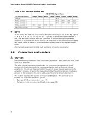
... should connect only to the computer, the power cable, and the external devices themselves. Do not use these groups: • Back panel I/O connectors (see page 49) • Component-side connectors and headers (see page 50) 48 However, in certain interrupt-constrained situations...load presented by the external devices could cause damage to devices inside the computer's chassis, such as fans and internal peripherals. Intel Desktop Board DG965RY Technical Product Specification Table 16. A fault in APIC mode. The other internal connectors/headers are dynamic. 2.8 Connectors and ...
... should connect only to the computer, the power cable, and the external devices themselves. Do not use these groups: • Back panel I/O connectors (see page 49) • Component-side connectors and headers (see page 50) 48 However, in certain interrupt-constrained situations...load presented by the external devices could cause damage to devices inside the computer's chassis, such as fans and internal peripherals. Intel Desktop Board DG965RY Technical Product Specification Table 16. A fault in APIC mode. The other internal connectors/headers are dynamic. 2.8 Connectors and ...

Product Specification
Page 49
Poor audio quality occurs if passive (non-amplified) speakers are connected to power headphones or amplified speakers only. Technical Reference 2.8.1 Back Panel Connectors Figure 15 shows the location of the back panel connectors. Back Panel Connectors OM18439 NOTE The back panel audio line out connector is designed to this output. 49 A C F G I B D E H JK Item A B C D E F G H I J K Description PS/2 mouse port PS/2 keyboard port Parallel port VGA port IEEE-1394a USB ports [4] LAN USB ports [2] Audio line in Mic in Audio line out Figure 15.
Poor audio quality occurs if passive (non-amplified) speakers are connected to power headphones or amplified speakers only. Technical Reference 2.8.1 Back Panel Connectors Figure 15 shows the location of the back panel connectors. Back Panel Connectors OM18439 NOTE The back panel audio line out connector is designed to this output. 49 A C F G I B D E H JK Item A B C D E F G H I J K Description PS/2 mouse port PS/2 keyboard port Parallel port VGA port IEEE-1394a USB ports [4] LAN USB ports [2] Audio line in Mic in Audio line out Figure 15.

Product Specification
Page 51
...PCI Express x1 add-in card connector D High Definition Audio Link header E PCI Conventional bus add-in card connector 2 F Front panel audio header G PCI Conventional bus add-in card connector 1 H PCI Express x1 add-in card connector I PCI Express x16 ... connector P Front chassis fan header Q Chassis intrusion header R Auxiliary front panel power LED header S Front panel header T Serial ATA connectors [4] U Parallel ATA IDE connector V Front panel USB header W Front panel USB header X Front panel IEEE-1394a header Y PCI Conventional bus add-in Figure 16. Table 17...
...PCI Express x1 add-in card connector D High Definition Audio Link header E PCI Conventional bus add-in card connector 2 F Front panel audio header G PCI Conventional bus add-in card connector 1 H PCI Express x1 add-in card connector I PCI Express x16 ... connector P Front chassis fan header Q Chassis intrusion header R Auxiliary front panel power LED header S Front panel header T Serial ATA connectors [4] U Parallel ATA IDE connector V Front panel USB header W Front panel USB header X Front panel IEEE-1394a header Y PCI Conventional bus add-in Figure 16. Table 17...

Product Specification
Page 52
... Signal Name 1 Ground 2 TXP 3 TXN 4 Ground 5 RXN 6 RXP 7 Ground Table 21. Front Panel Audio Header Pin Signal Name Pin 1 [Port 1] Left channel 2 3 [Port 1] Right channel 4 5 [Port 2] Right channel 6 7 SENSE_SEND (Jack detection) 8 9 [Port 2] Left channel 10 Table 20. Intel Desktop Board DG965RY Technical Product Specification Table 18. Serial Port Header Pin Signal Name Pin...
... Signal Name 1 Ground 2 TXP 3 TXN 4 Ground 5 RXN 6 RXP 7 Ground Table 21. Front Panel Audio Header Pin Signal Name Pin 1 [Port 1] Left channel 2 3 [Port 1] Right channel 4 5 [Port 2] Right channel 6 7 SENSE_SEND (Jack detection) 8 9 [Port 2] Left channel 10 Table 20. Intel Desktop Board DG965RY Technical Product Specification Table 18. Serial Port Header Pin Signal Name Pin...
Product Specification
Page 55
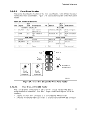
... Hard Drive Activity LED 1 HD_PWR Out Hard disk LED pull-up to provide a visual indicator that data is a connection diagram for the front panel header. Table 27 lists the signal names of the following: • A Serial ATA hard drive connected to an onboard Serial ATA connector •... is being read from or written to an onboard Parallel ATA IDE connector 55 Hard Drive Activity LED + OM18331 Figure 17. Connection Diagram for Front Panel Header 2.8.2.3.1 Hard Drive Activity LED Header Pins 1 and 3 can be connected to an LED to +5 V 3 HDA# Out Hard disk active ...
... Hard Drive Activity LED 1 HD_PWR Out Hard disk LED pull-up to provide a visual indicator that data is a connection diagram for the front panel header. Table 27 lists the signal names of the following: • A Serial ATA hard drive connected to an onboard Serial ATA connector •... is being read from or written to an onboard Parallel ATA IDE connector 55 Hard Drive Activity LED + OM18331 Figure 17. Connection Diagram for Front Panel Header 2.8.2.3.1 Hard Drive Activity LED Header Pins 1 and 3 can be connected to an LED to +5 V 3 HDA# Out Hard disk active ...
Product Specification
Page 56
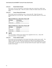
Intel Desktop Board DG965RY Technical Product Specification 2.8.2.3.2 Reset Switch Header Pins 5 and 7 can be connected to a front panel momentary-contact power switch. The switch must pass before the power supply will recognize another on/off signal. 56 Table 29 shows the possible states ...
Intel Desktop Board DG965RY Technical Product Specification 2.8.2.3.2 Reset Switch Header Pins 5 and 7 can be connected to a front panel momentary-contact power switch. The switch must pass before the power supply will recognize another on/off signal. 56 Table 29 shows the possible states ...
Product Specification
Page 57
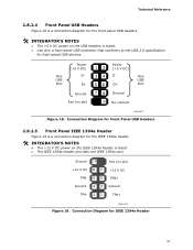
...Ground 10 No connect One USB Port OM18317 Figure 18. One USB Port Power (+5 V DC) D- Technical Reference 2.8.2.4 Front Panel USB Headers Figure 18 is a connection diagram for the front panel USB headers. # INTEGRATOR'S NOTES • The +5 V DC power on the IEEE 1394a header is fused. • ...+12 V DC TPB- 6 5 TPB+ Ground 4 3 Ground TPA- 2 1 TPA+ OM18332 Figure 19. Connection Diagram for Front Panel USB Headers 2.8.2.5 Front Panel IEEE 1394a Header Figure 19 is a connection diagram for IEEE 1394a Header 57 Connection Diagram for the IEEE 1394a header. # INTEGRATOR'S NOTES...
...Ground 10 No connect One USB Port OM18317 Figure 18. One USB Port Power (+5 V DC) D- Technical Reference 2.8.2.4 Front Panel USB Headers Figure 18 is a connection diagram for the front panel USB headers. # INTEGRATOR'S NOTES • The +5 V DC power on the IEEE 1394a header is fused. • ...+12 V DC TPB- 6 5 TPB+ Ground 4 3 Ground TPA- 2 1 TPA+ OM18332 Figure 19. Connection Diagram for Front Panel USB Headers 2.8.2.5 Front Panel IEEE 1394a Header Figure 19 is a connection diagram for IEEE 1394a Header 57 Connection Diagram for the IEEE 1394a header. # INTEGRATOR'S NOTES...


