Product Guide
Page 6
Intel Desktop Board DG45FC Product Guide Installing the I/O Shield 29 Installing and Removing the Desktop Board 30 Installing and Removing a Processor 31 Installing a Processor 31 Installing a Processor Fan Heat Sink 34 Connecting the Processor Fan Heat Sink Cable 35 Removing the ...Supply Cables 47 Setting the BIOS Configuration Jumper 48 Clearing Passwords 49 Replacing the Battery 50 3 Updating the BIOS 55 Updating the BIOS with the Intel® Express BIOS Update Utility 55 Updating the BIOS with the ISO Image BIOS Update File or the Iflash Memory Update Utility ...56 Obtaining the...
Intel Desktop Board DG45FC Product Guide Installing the I/O Shield 29 Installing and Removing the Desktop Board 30 Installing and Removing a Processor 31 Installing a Processor 31 Installing a Processor Fan Heat Sink 34 Connecting the Processor Fan Heat Sink Cable 35 Removing the ...Supply Cables 47 Setting the BIOS Configuration Jumper 48 Clearing Passwords 49 Replacing the Battery 50 3 Updating the BIOS 55 Updating the BIOS with the Intel® Express BIOS Update Utility 55 Updating the BIOS with the ISO Image BIOS Update File or the Iflash Memory Update Utility ...56 Obtaining the...
Product Guide
Page 7
... Configuration Example 36 14. Connecting a Serial ATA Cable 40 17. Location of the Chassis Fan Headers 46 20. Desktop Board DG45FC Components 12 3. Desktop Board DG45FC Components 11 2. Lift the Socket Lever 31 7. Installing a DIMM 38 16. Feature Summary 9 2. LAN Connector ...LEDs 18 vii Use DDR2 DIMMs 37 15. Location of the BIOS Configuration Jumper Block 48 22. Audio Jack Retasking Support 16 4. Installing the I/O Shield...
... Configuration Example 36 14. Connecting a Serial ATA Cable 40 17. Location of the Chassis Fan Headers 46 20. Desktop Board DG45FC Components 12 3. Desktop Board DG45FC Components 11 2. Lift the Socket Lever 31 7. Installing a DIMM 38 16. Feature Summary 9 2. LAN Connector ...LEDs 18 vii Use DDR2 DIMMs 37 15. Location of the BIOS Configuration Jumper Block 48 22. Audio Jack Retasking Support 16 4. Installing the I/O Shield...
Product Guide
Page 27
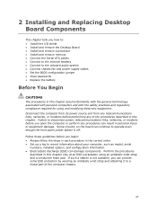
Follow these guidelines before you how to: • Install the I/O shield • Install and remove the Desktop Board • Install and remove a processor • Install and remove memory • Connect the Serial ATA cables • Connect to the internal headers • Connect... continue to disconnect power, telecommunications links, networks, or modems before performing any of the computer chassis. 27 2 Installing and Replacing Desktop Board Components This chapter tells you begin: • Always follow the steps in each procedure in the correct order. • Set up a log to ...
Follow these guidelines before you how to: • Install the I/O shield • Install and remove the Desktop Board • Install and remove a processor • Install and remove memory • Connect the Serial ATA cables • Connect to the internal headers • Connect... continue to disconnect power, telecommunications links, networks, or modems before performing any of the computer chassis. 27 2 Installing and Replacing Desktop Board Components This chapter tells you begin: • Always follow the steps in each procedure in the correct order. • Set up a log to ...

Product Guide
Page 29
... within the chassis. Figure 4. Place the shield inside the chassis as shown in the chassis. Installing the I /O shield. Press the shield into place so that it fits tightly and securely. Installing and Replacing Desktop Board Components Installing the I/O Shield The Desktop Board comes with an I /O Shield 29 When installed in the chassis, the shield blocks radio frequency transmissions, protects internal...
... within the chassis. Figure 4. Place the shield inside the chassis as shown in the chassis. Installing the I /O shield. Press the shield into place so that it fits tightly and securely. Installing and Replacing Desktop Board Components Installing the I/O Shield The Desktop Board comes with an I /O Shield 29 When installed in the chassis, the shield blocks radio frequency transmissions, protects internal...

Product Guide
Page 42
... for the front panel audio header. Chassis Intrusion Header Signal Names Pin Description 1 Intruder 2 Ground Consumer IR (CIR) Headers The Desktop Board has two CIR headers: the receiver or input header (Figure 17, F) and the output or emitter header (Figure 17, C). Front... 42 Chassis Intrusion Header Figure 17, B on page 27. 2. Intel Desktop Board DG45FC Product Guide Front Panel HD Audio Header Figure 17, A shows the location of the chassis intrusion header. Install a correctly keyed and shielded front panel audio cable. Table 6. The emitter header consists of ...
... for the front panel audio header. Chassis Intrusion Header Signal Names Pin Description 1 Intruder 2 Ground Consumer IR (CIR) Headers The Desktop Board has two CIR headers: the receiver or input header (Figure 17, F) and the output or emitter header (Figure 17, C). Front... 42 Chassis Intrusion Header Figure 17, B on page 27. 2. Intel Desktop Board DG45FC Product Guide Front Panel HD Audio Header Figure 17, A shows the location of the chassis intrusion header. Install a correctly keyed and shielded front panel audio cable. Table 6. The emitter header consists of ...

Product Guide
Page 43
... Ground 3 No Connection 5 +5 V Standby 7 Key (no device or a low-speed USB device is attached to the cable. Table 9. Use a shielded cable that have an unshielded cable attached to a USB port might not meet FCC Class B requirements, even if no pin) Pin Signal Name 2 LED 4...Power (+5 V) 2 3 D- 4 5 D+ 6 7 Ground 8 9 Key 10 Note: USB ports may be used to connect two USB devices. Table 7. Installing and Replacing Desktop Board Components NOTE The Consumer IR option must be enabled in the system BIOS before it can be assigned as needed. Press at boot to enter...
... Ground 3 No Connection 5 +5 V Standby 7 Key (no device or a low-speed USB device is attached to the cable. Table 9. Use a shielded cable that have an unshielded cable attached to a USB port might not meet FCC Class B requirements, even if no pin) Pin Signal Name 2 LED 4...Power (+5 V) 2 3 D- 4 5 D+ 6 7 Ground 8 9 Key 10 Note: USB ports may be used to connect two USB devices. Table 7. Installing and Replacing Desktop Board Components NOTE The Consumer IR option must be enabled in the system BIOS before it can be assigned as needed. Press at boot to enter...

Product Guide
Page 77
... other modules: • Product certifications or lack of the newly completed computer. 77 You may be required on a representative sample of certifications • External I/O cable shielding and filtering • Mounting, grounding, and bonding requirements • Keying connectors when mating the wrong connectors could be hazardous If the power supply and other...
... other modules: • Product certifications or lack of the newly completed computer. 77 You may be required on a representative sample of certifications • External I/O cable shielding and filtering • Mounting, grounding, and bonding requirements • Keying connectors when mating the wrong connectors could be hazardous If the power supply and other...