Product Guide
Page 5
Contents 1 Desktop Board Features Desktop Board Components 11 Processor ...13 Main Memory...13 Intel® G45 Express Chipset 14 Intel G45 Graphics Subsystem 15 DVI-I Support 15 HDMI* Technology Support 15 Intel® Viiv™ Technology 15 Audio Subsystem 16 Legacy Input/Output (I/O) Controller 17 LAN Subsystem 17 LAN ... 25 ENERGY STAR* Qualified 25 Speaker...25 Battery ...25 Real-Time Clock 25 2 Installing and Replacing Desktop Board Components Before You Begin 27 Installation Precautions 28 Prevent Power Supply Overload 28 Observe Safety and Regulatory Requirements 28 v
Contents 1 Desktop Board Features Desktop Board Components 11 Processor ...13 Main Memory...13 Intel® G45 Express Chipset 14 Intel G45 Graphics Subsystem 15 DVI-I Support 15 HDMI* Technology Support 15 Intel® Viiv™ Technology 15 Audio Subsystem 16 Legacy Input/Output (I/O) Controller 17 LAN Subsystem 17 LAN ... 25 ENERGY STAR* Qualified 25 Speaker...25 Battery ...25 Real-Time Clock 25 2 Installing and Replacing Desktop Board Components Before You Begin 27 Installation Precautions 28 Prevent Power Supply Overload 28 Observe Safety and Regulatory Requirements 28 v
Product Guide
Page 6
Intel Desktop Board DG45FC Product Guide Installing the I/O Shield 29 Installing and Removing the Desktop Board 30 Installing and Removing a Processor 31 Installing a Processor 31 Installing a Processor Fan Heat Sink 34 Connecting the Processor Fan Heat Sink Cable 35 Removing...Removing Memory 36 Installing DIMMs 37 Removing DIMMs 39 Connecting Serial ATA (SATA) Cables 40 Connecting to Internal Headers and Connectors 41 Front Panel HD Audio Header 42 Chassis Intrusion Header 42 Consumer IR (CIR) Headers 42 USB 2.0 Headers 43 Serial Port Header 44 Alternate Front Panel Power LED ...
Intel Desktop Board DG45FC Product Guide Installing the I/O Shield 29 Installing and Removing the Desktop Board 30 Installing and Removing a Processor 31 Installing a Processor 31 Installing a Processor Fan Heat Sink 34 Connecting the Processor Fan Heat Sink Cable 35 Removing...Removing Memory 36 Installing DIMMs 37 Removing DIMMs 39 Connecting Serial ATA (SATA) Cables 40 Connecting to Internal Headers and Connectors 41 Front Panel HD Audio Header 42 Chassis Intrusion Header 42 Consumer IR (CIR) Headers 42 USB 2.0 Headers 43 Serial Port Header 44 Alternate Front Panel Power LED ...
Product Guide
Page 7
...Serial ATA Cable 40 17. Connecting Power Supply Cables 47 21. Removing the Battery 54 23. Installing the I/O Shield 29 5. Desktop Board DG45FC Mounting Screw Hole Locations 30 6. Remove the Protective Socket Cover 32 9. Install the Processor 33 11. Dual Channel Memory Configuration ... Audio Connectors 45 19. Audio Jack Retasking Support 16 4. Lift the Socket Lever 31 7. Connecting the Processor Fan Heat Sink Cable 35 13. LAN Connector LEDs 18 vii Close the Load Plate 34 12. Desktop Board DG45FC Components 12 3. Lift the Load Plate 32 8. Desktop Board DG45FC China...
...Serial ATA Cable 40 17. Connecting Power Supply Cables 47 21. Removing the Battery 54 23. Installing the I/O Shield 29 5. Desktop Board DG45FC Mounting Screw Hole Locations 30 6. Remove the Protective Socket Cover 32 9. Install the Processor 33 11. Dual Channel Memory Configuration ... Audio Connectors 45 19. Audio Jack Retasking Support 16 4. Lift the Socket Lever 31 7. Connecting the Processor Fan Heat Sink Cable 35 13. LAN Connector LEDs 18 vii Close the Load Plate 34 12. Desktop Board DG45FC Components 12 3. Lift the Load Plate 32 8. Desktop Board DG45FC China...
Product Guide
Page 8
Front Panel Audio Header Signal Names for the BIOS Setup Program Modes 49 14. Front Panel Header 44 13. Intel Desktop Board DG45FC Product Guide 5. USB 2.0 Header Signal Names 43 10. BIOS Error Messages 65 16. Safety Standards 67 17. Back Panel CIR Header Emitter (Output) Header Signal ...
Front Panel Audio Header Signal Names for the BIOS Setup Program Modes 49 14. Front Panel Header 44 13. Intel Desktop Board DG45FC Product Guide 5. USB 2.0 Header Signal Names 43 10. BIOS Error Messages 65 16. Safety Standards 67 17. Back Panel CIR Header Emitter (Output) Header Signal ...
Product Guide
Page 9
Table 1. Table 1 summarizes the major features of Intel® Desktop Board DG45FC. 1 Desktop Board Features This chapter briefly describes the features of the Desktop Board. Feature Summary Form Factor Processor Main Memory Chipset Graphics Audio Mini-ITX (171.45 millimeters [6.75 inches] x 171.45 millimeters [6.75 inches]) Support for an Intel® processor in the LGA775 package • Two 240-pin...
Table 1. Table 1 summarizes the major features of Intel® Desktop Board DG45FC. 1 Desktop Board Features This chapter briefly describes the features of the Desktop Board. Feature Summary Form Factor Processor Main Memory Chipset Graphics Audio Mini-ITX (171.45 millimeters [6.75 inches] x 171.45 millimeters [6.75 inches]) Support for an Intel® processor in the LGA775 package • Two 240-pin...
Product Guide
Page 15
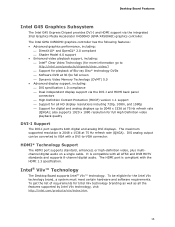
...for more information go to -VGA connector. Intel® Viiv™ Technology The Desktop Board supports Intel® Viiv™ technology. To be converted to VGA with all ATSC and DVB HDTV standards and supports 8-channel digital audio. To get the list of Blu-ray ...Disc* technology DVDs ⎯ Software DVD at 30 fps full screen ⎯ Dynamic Video Memory Technology (DVMT) 5.0 • Advanced display support, including: ⎯ DVI specification 1.0 compliance ⎯ Dual independent display support via the integrated Intel Graphics Media...
...for more information go to -VGA connector. Intel® Viiv™ Technology The Desktop Board supports Intel® Viiv™ technology. To be converted to VGA with all ATSC and DVB HDTV standards and supports 8-channel digital audio. To get the list of Blu-ray ...Disc* technology DVDs ⎯ Software DVD at 30 fps full screen ⎯ Dynamic Video Memory Technology (DVMT) 5.0 • Advanced display support, including: ⎯ DVI specification 1.0 compliance ⎯ Dual independent display support via the integrated Intel Graphics Media...
Product Guide
Page 16
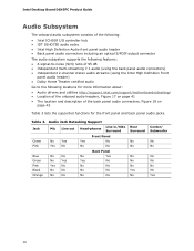
Table 3. Intel Desktop Board DG45FC Product Guide Audio Subsystem The onboard audio subsystem consists of the following: • Intel ICH10R I/O controller hub • IDT 92HD73E audio codec • Intel High Definition Audio front panel audio header • Back panel audio connectors including an optical S/PDIF output connector The audio subsystem supports the following features: • A signal-to-noise (S/N) ratio of 95 dB • Independent...
Table 3. Intel Desktop Board DG45FC Product Guide Audio Subsystem The onboard audio subsystem consists of the following: • Intel ICH10R I/O controller hub • IDT 92HD73E audio codec • Intel High Definition Audio front panel audio header • Back panel audio connectors including an optical S/PDIF output connector The audio subsystem supports the following features: • A signal-to-noise (S/N) ratio of 95 dB • Independent...
Product Guide
Page 27
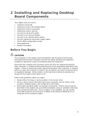
... operate even though the front panel power button is off. 2 Installing and Replacing Desktop Board Components This chapter tells you how to: • Install the I/O shield • Install and remove the Desktop Board • Install and remove a processor • Install and remove memory •... Connect the Serial ATA cables • Connect to the internal headers • Connect to the onboard audio system • Connect chassis fan and power supply ...
... operate even though the front panel power button is off. 2 Installing and Replacing Desktop Board Components This chapter tells you how to: • Install the I/O shield • Install and remove the Desktop Board • Install and remove a processor • Install and remove memory •... Connect the Serial ATA cables • Connect to the internal headers • Connect to the onboard audio system • Connect chassis fan and power supply ...
Product Guide
Page 41
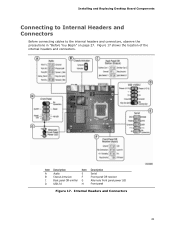
Item Description Item Description A Audio E Serial B Chassis intrusion F Front panel CIR receiver C Back panel CIR emitter G Alternate front panel power LED D USB 2.0 H Front panel Figure 17. Installing and Replacing Desktop Board Components Connecting to Internal Headers and Connectors Before connecting cables to the internal headers and connectors, observe the precautions in "Before You Begin" on page 27. Figure 17 shows the location of the internal headers and connectors. Internal Headers and Connectors 41
Item Description Item Description A Audio E Serial B Chassis intrusion F Front panel CIR receiver C Back panel CIR emitter G Alternate front panel power LED D USB 2.0 H Front panel Figure 17. Installing and Replacing Desktop Board Components Connecting to Internal Headers and Connectors Before connecting cables to the internal headers and connectors, observe the precautions in "Before You Begin" on page 27. Figure 17 shows the location of the internal headers and connectors. Internal Headers and Connectors 41

Product Guide
Page 42
Table 6 shows the pin assignments for the front panel audio header. Intel Desktop Board DG45FC Product Guide Front Panel HD Audio Header Figure 17, A shows the location of a filtered translated infrared input compliant with Microsoft CIR specifications and a "learning" infrared input. Chassis Intrusion Header Figure 17, B ...
Table 6 shows the pin assignments for the front panel audio header. Intel Desktop Board DG45FC Product Guide Front Panel HD Audio Header Figure 17, A shows the location of a filtered translated infrared input compliant with Microsoft CIR specifications and a "learning" infrared input. Chassis Intrusion Header Figure 17, B ...
Product Guide
Page 45
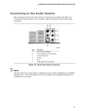
...Desktop Board Components Connecting to this output. 45 Item Description A Rear Surround Left/Right B Center Channel and LFE (Subwoofer) C Side Surround/Line In D Line Out E Mic In F S/PDIF Digital Audio Out (Optical) Figure 18. Poor audio quality may occur if passive (non-amplified) speakers are connected to the Audio... System After installing the IDT audio driver from the Intel Express Installer DVD-ROM, the multi-channel audio feature can be enabled. Figure 18 shows the back panel audio connectors. Back Panel Audio Connectors NOTE The back ...
...Desktop Board Components Connecting to this output. 45 Item Description A Rear Surround Left/Right B Center Channel and LFE (Subwoofer) C Side Surround/Line In D Line Out E Mic In F S/PDIF Digital Audio Out (Optical) Figure 18. Poor audio quality may occur if passive (non-amplified) speakers are connected to the Audio... System After installing the IDT audio driver from the Intel Express Installer DVD-ROM, the multi-channel audio feature can be enabled. Figure 18 shows the back panel audio connectors. Back Panel Audio Connectors NOTE The back ...


