
Product Guide
Page 5
Contents 1 Desktop Board Features Desktop Board Components 11 Processor ...12 Main Memory...13 Intel® G41 Express Chipset 14 Graphics Support 14 Intel® GMA X4500 Graphics Controller 14 DVI Support 14 Audio Subsystem 15 Legacy Input/Output (I/O) ...22 Real-Time Clock 22 2 Installing and Replacing Desktop Board Components Before You Begin 23 Installation Precautions 24 Prevent Power Supply Overload 24 Observe Safety and Regulatory Requirements 24 Installing the I/O Shield 25 Installing and Removing the Desktop Board 26 Installing and Removing a Processor 27 Installing ...
Contents 1 Desktop Board Features Desktop Board Components 11 Processor ...12 Main Memory...13 Intel® G41 Express Chipset 14 Graphics Support 14 Intel® GMA X4500 Graphics Controller 14 DVI Support 14 Audio Subsystem 15 Legacy Input/Output (I/O) ...22 Real-Time Clock 22 2 Installing and Replacing Desktop Board Components Before You Begin 23 Installation Precautions 24 Prevent Power Supply Overload 24 Observe Safety and Regulatory Requirements 24 Installing the I/O Shield 25 Installing and Removing the Desktop Board 26 Installing and Removing a Processor 27 Installing ...
Product Guide
Page 7
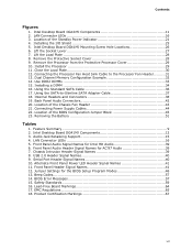
... I/O Shield 25 5. LAN Connector LEDs 16 5. USB 2.0 Header Signal Names 40 9. Front Panel Header Signal Names 41 12. EMC Regulations 65 18. Use DDR2 DIMMs 33 15. Using the SATA-to the Processor Fan Header ..........31 13. Location of the Standby Power Indicator 21 4. Jumper Settings for Intel HD Audio 39 6. Intel Desktop Board DG41MJ Components...
... I/O Shield 25 5. LAN Connector LEDs 16 5. USB 2.0 Header Signal Names 40 9. Front Panel Header Signal Names 41 12. EMC Regulations 65 18. Use DDR2 DIMMs 33 15. Using the SATA-to the Processor Fan Header ..........31 13. Location of the Standby Power Indicator 21 4. Jumper Settings for Intel HD Audio 39 6. Intel Desktop Board DG41MJ Components...

Product Guide
Page 23
... is not available, you can continue to a metal part of the procedures described in this chapter. Some circuitry on the board can provide some ESD protection by wearing an antistatic wrist strap and attaching it to operate even though the front panel power button...this chapter only at an ESD workstation using and modifying electronic equipment. 2 Installing and Replacing Desktop Board Components This chapter tells you how to: • Install the I/O shield • Install and remove the Desktop Board • Install and remove a processor • Install and remove memory • Use ...
... is not available, you can continue to a metal part of the procedures described in this chapter. Some circuitry on the board can provide some ESD protection by wearing an antistatic wrist strap and attaching it to operate even though the front panel power button...this chapter only at an ESD workstation using and modifying electronic equipment. 2 Installing and Replacing Desktop Board Components This chapter tells you how to: • Install the I/O shield • Install and remove the Desktop Board • Install and remove a processor • Install and remove memory • Use ...

Product Guide
Page 25
Installing and Replacing Desktop Board Components Installing the I/O Shield The Desktop Board comes with an I /O shield before installing the Desktop Board in the chassis. Place the shield inside the chassis as shown in the chassis, the shield blocks radio frequency transmissions, protects internal components from the chassis supplier. Install the I /O shield. If the shield does not fit, obtain a properly sized shield from dust and...
Installing and Replacing Desktop Board Components Installing the I/O Shield The Desktop Board comes with an I /O shield before installing the Desktop Board in the chassis. Place the shield inside the chassis as shown in the chassis, the shield blocks radio frequency transmissions, protects internal components from the chassis supplier. Install the I /O shield. If the shield does not fit, obtain a properly sized shield from dust and...

Product Guide
Page 40
Intel Desktop Board DG41MJ Product Guide USB 2.0 Headers Before connecting to the USB 2.0 headers, observe the precautions in "Before You Begin" on page 38 for the location of the ... header. USB Port B Signal Name Power (+5 V) DD+ Ground No Connection NOTE Computer systems that meets the requirements for the location of the USB 2.0 headers. Use a shielded cable that have an unshielded cable attached to a USB port might not meet FCC Class B requirements, even if no device or a low-speed USB device...
Intel Desktop Board DG41MJ Product Guide USB 2.0 Headers Before connecting to the USB 2.0 headers, observe the precautions in "Before You Begin" on page 38 for the location of the ... header. USB Port B Signal Name Power (+5 V) DD+ Ground No Connection NOTE Computer systems that meets the requirements for the location of the USB 2.0 headers. Use a shielded cable that have an unshielded cable attached to a USB port might not meet FCC Class B requirements, even if no device or a low-speed USB device...

Product Guide
Page 66
... or lack of certifications • External I/O cable shielding and filtering • Mounting, grounding, and bonding requirements • Keying connectors when mating the wrong connectors could be required on a representative sample of the newly completed computer. 66 Pay close attention to comply with EMC requirements. Intel Desktop Board DG41MJ Product Guide Korean Class B statement translation: This...
... or lack of certifications • External I/O cable shielding and filtering • Mounting, grounding, and bonding requirements • Keying connectors when mating the wrong connectors could be required on a representative sample of the newly completed computer. 66 Pay close attention to comply with EMC requirements. Intel Desktop Board DG41MJ Product Guide Korean Class B statement translation: This...