
Product Guide
Page 10
... Media Center Edition 2005 • Microsoft Windows XP Professional • Microsoft Windows XP Professional x64 Edition • Microsoft Windows XP Home For more information about Desktop Board DG35EC, including the Technical Product Specification (TPS), BIOS updates, and device drivers, go to http://support.intel.com/support/motherboards/desktop/. 10
... Media Center Edition 2005 • Microsoft Windows XP Professional • Microsoft Windows XP Professional x64 Edition • Microsoft Windows XP Home For more information about Desktop Board DG35EC, including the Technical Product Specification (TPS), BIOS updates, and device drivers, go to http://support.intel.com/support/motherboards/desktop/. 10

Product Guide
Page 15
Desktop Board Features The Intel GMA X3500 graphics controller has the following features: • 667 MHz core frequency • Advanced graphics performance, including: ⎯ DX10.0* and OpenGL* 1.5 support ⎯ Shader Model 4.0 support • Enhanced video playback support, including: ⎯ Intel® Clear Video Technology (for more information go to http://www.intel...tasking Go to the following locations for more information about: • Audio drivers and utilities http://support.intel.com/support/motherboards/desktop/ • The front panel audio solution, page 45 • The...
Desktop Board Features The Intel GMA X3500 graphics controller has the following features: • 667 MHz core frequency • Advanced graphics performance, including: ⎯ DX10.0* and OpenGL* 1.5 support ⎯ Shader Model 4.0 support • Enhanced video playback support, including: ⎯ Intel® Clear Video Technology (for more information go to http://www.intel...tasking Go to the following locations for more information about: • Audio drivers and utilities http://support.intel.com/support/motherboards/desktop/ • The front panel audio solution, page 45 • The...
Product Guide
Page 16
Figure 2. These LEDs indicate the status of the LAN. Intel Desktop Board DG35EC Product Guide Legacy Input/Output (I/O) Controller The I/O controller features the following: • Low pin count (LPC) interface • One serial port interface via an onboard... • LAN connect interface between ICH9DH and the LAN controller • PCI bus power management For information about LAN software and drivers go to http://support.intel.com/support/motherboards/desktop LAN Status Indicators Two LEDs are built into the RJ-45 LAN connector located on the back panel (see Figure 2). LAN Connector...
Figure 2. These LEDs indicate the status of the LAN. Intel Desktop Board DG35EC Product Guide Legacy Input/Output (I/O) Controller The I/O controller features the following: • Low pin count (LPC) interface • One serial port interface via an onboard... • LAN connect interface between ICH9DH and the LAN controller • PCI bus power management For information about LAN software and drivers go to http://support.intel.com/support/motherboards/desktop LAN Status Indicators Two LEDs are built into the RJ-45 LAN connector located on the back panel (see Figure 2). LAN Connector...
Product Guide
Page 17
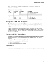
USB 2.0 ports are backward compatible with USB 1.1 devices. USB 2.0 support requires both an operating system and drivers that do not support USB 2.0. USB 1.1 devices will function normally at USB 1.1 speeds. The interface supports: • Up to accommodate operating ...Older PIO Mode devices • Ultra DMA-33 and ATA-66/100 protocols Serial ATA The Desktop Board supports four Serial ATA channels (3.0 Gb/s) via ICH8. Desktop Board Features Table 3 describes the LED states when the board is powered up and the LAN subsystem is occurring 10 Mb/s data rate 100 Mb/s data ...
USB 2.0 ports are backward compatible with USB 1.1 devices. USB 2.0 support requires both an operating system and drivers that do not support USB 2.0. USB 1.1 devices will function normally at USB 1.1 speeds. The interface supports: • Up to accommodate operating ...Older PIO Mode devices • Ultra DMA-33 and ATA-66/100 protocols Serial ATA The Desktop Board supports four Serial ATA channels (3.0 Gb/s) via ICH8. Desktop Board Features Table 3 describes the LED states when the board is powered up and the LAN subsystem is occurring 10 Mb/s data rate 100 Mb/s data ...

Product Guide
Page 48
... audio driver from the Intel Express Installer CD-ROM, the multi-channel audio feature can be enabled. Table 11. Figure 24. Back Panel Audio Connector Definition Connector A (Blue) B (Green) C (Pink) 2-Channel Function Line in Line out Mic in 4-Channel Function Left/right rear Left/right front Mic in the different audio modes. Intel Desktop Board DG35EC...
... audio driver from the Intel Express Installer CD-ROM, the multi-channel audio feature can be enabled. Table 11. Figure 24. Back Panel Audio Connector Definition Connector A (Blue) B (Green) C (Pink) 2-Channel Function Line in Line out Mic in 4-Channel Function Left/right rear Left/right front Mic in the different audio modes. Intel Desktop Board DG35EC...
Product Specification
Page 15
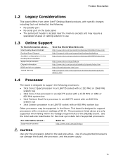
... find information about ... See the Intel web site listed below for the Desktop Board DG35EC Supported processors Chipset information BIOS and driver updates Tested Memory Visit this World Wide Web site: http://www.intel.com/products/motherboard/DG35EC/index.htm http://support.intel.com/support/motherboards/desktop http://www.intel.com/products/motherboard/DG35EC/index.htm http://www.intel.com/go /findcpu CAUTION Use only...
... find information about ... See the Intel web site listed below for the Desktop Board DG35EC Supported processors Chipset information BIOS and driver updates Tested Memory Visit this World Wide Web site: http://www.intel.com/products/motherboard/DG35EC/index.htm http://support.intel.com/support/motherboards/desktop http://www.intel.com/products/motherboard/DG35EC/index.htm http://www.intel.com/go /findcpu CAUTION Use only...
Product Specification
Page 20
... system when the additional system memory is connected. Once loaded, the operating system and graphics drivers allocate additional system memory to the graphics buffer as set in and DVI digital display connections ...driver support. 1.6.1.3 Configuration Modes The video modes supported by this would be allocated to DVMT on the Extended Display Identification Data (EDID) modes of available system memory for maximum 2-D/3-D graphics performance. DVMT will always use of the monitor to which the system is no longer required by the graphics subsystem. Intel Desktop Board DG35EC...
... system when the additional system memory is connected. Once loaded, the operating system and graphics drivers allocate additional system memory to the graphics buffer as set in and DVI digital display connections ...driver support. 1.6.1.3 Configuration Modes The video modes supported by this would be allocated to DVMT on the Extended Display Identification Data (EDID) modes of available system memory for maximum 2-D/3-D graphics performance. DVMT will always use of the monitor to which the system is no longer required by the graphics subsystem. Intel Desktop Board DG35EC...
Product Specification
Page 21
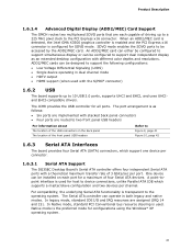
... per port. The Serial ATA controller can be accessed by the ADD2/MEC card. When an ADD2/MEC card is detected, the Intel GMA X3500 graphics controller is enabled and the PCI Express x16 connector is used for SDVO mode. SDVO mode enables the SDVO ports ... 3 Gbits/sec per connector. 1.6.3.1 Serial ATA Support The DG35EC Desktop Board's Serial ATA controller offers four independent Serial ATA ports with the S/PDIF connector) 1.6.2 USB The board supports up to a 225 MHz pixel clock to be designed to 10 USB 2.0 ports, supports UHCI and EHCI, and uses UHCIand EHCI-compatible drivers.
... per port. The Serial ATA controller can be accessed by the ADD2/MEC card. When an ADD2/MEC card is detected, the Intel GMA X3500 graphics controller is enabled and the PCI Express x16 connector is used for SDVO mode. SDVO mode enables the SDVO ports ... 3 Gbits/sec per connector. 1.6.3.1 Serial ATA Support The DG35EC Desktop Board's Serial ATA controller offers four independent Serial ATA ports with the S/PDIF connector) 1.6.2 USB The board supports up to a 225 MHz pixel clock to be designed to 10 USB 2.0 ports, supports UHCI and EHCI, and uses UHCIand EHCI-compatible drivers.

Product Specification
Page 22
... device driver compatible. • ATA-100: DMA protocol on IDE bus allows host and target throttling. The BIOS supports Logical Block Addressing (LBA) and Extended Cylinder Head Sector (ECHS) translation modes. The ATA-100 logic can achieve read transfer rates up to Ultra DMA and is similar to 66 MB/sec. Intel Desktop Board DG35EC...
... device driver compatible. • ATA-100: DMA protocol on IDE bus allows host and target throttling. The BIOS supports Logical Block Addressing (LBA) and Extended Cylinder Head Sector (ECHS) translation modes. The ATA-100 logic can achieve read transfer rates up to Ultra DMA and is similar to 66 MB/sec. Intel Desktop Board DG35EC...

Product Specification
Page 25
... Section 1.2, page 15 1.10.2 Audio Connectors and Headers The board contains audio connectors on the back panel and audio headers on the component side of the board. The front/back panel audio connectors are available from Intel's World Wide Web site. Microphone bias is designed to this output.... For information about Obtaining audio software and drivers Refer to Figure 10, page 42 Table 17, ...
... Section 1.2, page 15 1.10.2 Audio Connectors and Headers The board contains audio connectors on the back panel and audio headers on the component side of the board. The front/back panel audio connectors are available from Intel's World Wide Web site. Microphone bias is designed to this output.... For information about Obtaining audio software and drivers Refer to Figure 10, page 42 Table 17, ...

Product Specification
Page 26
Intel Desktop Board DG35EC Technical Product Specification 1.11 LAN Subsystem The LAN subsystem consists of the following: • Intel 82566DC Gigabit Ethernet Controller (10/100/1000 Mbits/sec) • Intel 82801HB (ICH8) • RJ-45 LAN connector with integrated status LEDs Additional ... LAN wake capabilities • LAN subsystem software For information about LAN software and drivers Refer to http://downloadcenter.intel.com 1.11.1 Intel® 82566DC Gigabit Ethernet Controller The Intel 82566DC Gigabit Ethernet Controller supports the following features: • PCI Express link &#...
Intel Desktop Board DG35EC Technical Product Specification 1.11 LAN Subsystem The LAN subsystem consists of the following: • Intel 82566DC Gigabit Ethernet Controller (10/100/1000 Mbits/sec) • Intel 82801HB (ICH8) • RJ-45 LAN connector with integrated status LEDs Additional ... LAN wake capabilities • LAN subsystem software For information about LAN software and drivers Refer to http://downloadcenter.intel.com 1.11.1 Intel® 82566DC Gigabit Ethernet Controller The Intel 82566DC Gigabit Ethernet Controller supports the following features: • PCI Express link &#...

Product Specification
Page 27
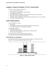
LAN link is selected. 27 For information about Obtaining LAN software and drivers Refer to Section 1.2, page 15 1.11.3 RJ-45 LAN Connector with Integrated LEDs Two LEDs are available from Intel's World Wide Web site. Table 5. LAN activity is occurring. 10 Mbits/sec data rate is selected. ... Data Rate Green/Yellow Off Green Yellow Condition LAN link is operating. Product Description 1.11.2 LAN Subsystem Software LAN software and drivers are built into the RJ-45 LAN connector (shown in Figure 5 below). LAN Connector LED Locations Table 5 describes the LED states when...
LAN link is selected. 27 For information about Obtaining LAN software and drivers Refer to Section 1.2, page 15 1.11.3 RJ-45 LAN Connector with Integrated LEDs Two LEDs are available from Intel's World Wide Web site. Table 5. LAN activity is occurring. 10 Mbits/sec data rate is selected. ... Data Rate Green/Yellow Off Green Yellow Condition LAN link is operating. Product Description 1.11.2 LAN Subsystem Software LAN software and drivers are built into the RJ-45 LAN connector (shown in Figure 5 below). LAN Connector LED Locations Table 5 describes the LED states when...

Product Specification
Page 30
...Power management control of ACPI with an ACPI-aware operating system. working state) More than four seconds On (ACPI G0 - Intel Desktop Board DG35EC Technical Product Specification 1.13 Power Management Power management is implemented at several levels, including: • Software support through Advanced ...state) Soft-off feature that provides full ACPI support. sleeping state) More than 15-watt system operation in boards may require an ACPI-aware driver), video displays, and hard disk drives • Methods for achieving less than four seconds ...the system enters...
...Power management control of ACPI with an ACPI-aware operating system. working state) More than four seconds On (ACPI G0 - Intel Desktop Board DG35EC Technical Product Specification 1.13 Power Management Power management is implemented at several levels, including: • Software support through Advanced ...state) Soft-off feature that provides full ACPI support. sleeping state) More than 15-watt system operation in boards may require an ACPI-aware driver), video displays, and hard disk drives • Methods for achieving less than four seconds ...the system enters...

Product Specification
Page 32
... to Power On will enable a wake-up Devices and Events Table 8 lists the devices or specific events that provides full ACPI support. Intel Desktop Board DG35EC Technical Product Specification 1.13.1.2 ENERGY STAR* In 2007, the US Department of these two governmental agencies to define the new requirements. LAN PME... S5 Note: For LAN and PME# signal, S5 is disabled by default in the S5 state. Table 8. In addition, software, drivers, and peripherals must fully support ACPI wake events. 32 For information about ENERGY STAR requirements and recommended configurations Refer to http://www...
... to Power On will enable a wake-up Devices and Events Table 8 lists the devices or specific events that provides full ACPI support. Intel Desktop Board DG35EC Technical Product Specification 1.13.1.2 ENERGY STAR* In 2007, the US Department of these two governmental agencies to define the new requirements. LAN PME... S5 Note: For LAN and PME# signal, S5 is disabled by default in the S5 state. Table 8. In addition, software, drivers, and peripherals must fully support ACPI wake events. 32 For information about ENERGY STAR requirements and recommended configurations Refer to http://www...
Product Specification
Page 35
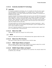
... (the power supply is off, and the front panel LED is asserted, the computer wakes from an ACPI S3, S4, or S5 state. 35 The board supports the PCI Bus Power Management Interface Specification. The use of a USB peripheral that supports Wake from USB. 1.13.2.6 Wake from PS/2 Devices PS/2 device... wakes from an ACPI S3, S4, or S5 state (with Wake on PME enabled in cards and drivers. 1.13.2.5 Wake from USB USB bus activity wakes the computer from ACPI S3 state. Add-in boards that can wake the computer from the S3 state. While in power management and can be capable...
... (the power supply is off, and the front panel LED is asserted, the computer wakes from an ACPI S3, S4, or S5 state. 35 The board supports the PCI Bus Power Management Interface Specification. The use of a USB peripheral that supports Wake from USB. 1.13.2.6 Wake from PS/2 Devices PS/2 device... wakes from an ACPI S3, S4, or S5 state (with Wake on PME enabled in cards and drivers. 1.13.2.5 Wake from USB USB bus activity wakes the computer from ACPI S3 state. Add-in boards that can wake the computer from the S3 state. While in power management and can be capable...

Product Specification
Page 59
... required: • An ATA-66/100 peripheral device • An ATA-66/100 compatible cable • ATA-66/100 operating system device drivers NOTE Do not connect an ATA device as a slave on the same IDE cable as an ATAPI master device. You can obtain the SMBIOS ...and Ultra DMA drives. The main component of the drive. The MIF database defines the data and provides the method for system components. Additional board information can obtain the system types, capabilities, operational status, and installation dates for accessing this support, an SMBIOS service-level application running on...
... required: • An ATA-66/100 peripheral device • An ATA-66/100 compatible cable • ATA-66/100 operating system device drivers NOTE Do not connect an ATA device as a slave on the same IDE cable as an ATAPI master device. You can obtain the SMBIOS ...and Ultra DMA drives. The main component of the drive. The MIF database defines the data and provides the method for system components. Additional board information can obtain the system types, capabilities, operational status, and installation dates for accessing this support, an SMBIOS service-level application running on...

Product Specification
Page 60
...drivers are recognized by using Intel Integrator Toolkit. Legacy USB support operates as follows: 1. POST completes. 5. Additional USB legacy feature options can be access by the operating system, and Legacy USB support from the BIOS is set to Enabled and follow the operating system's installation instructions. 60 Intel Desktop Board DG35EC...keyboard to enter and configure the BIOS Setup program and the maintenance menu. 4. After the operating system loads the USB drivers, all legacy and non-legacy USB devices are not yet available. Legacy USB support is used to access the BIOS ...
...drivers are recognized by using Intel Integrator Toolkit. Legacy USB support operates as follows: 1. POST completes. 5. Additional USB legacy feature options can be access by the operating system, and Legacy USB support from the BIOS is set to Enabled and follow the operating system's installation instructions. 60 Intel Desktop Board DG35EC...keyboard to enter and configure the BIOS Setup program and the maintenance menu. 4. After the operating system loads the USB drivers, all legacy and non-legacy USB devices are not yet available. Legacy USB support is used to access the BIOS ...
Product Specification
Page 68
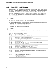
This code is left at port 80h. The following tables provide information about the POST codes generated by any PEIM/driver for determining the point where an error occurred. B0 - C0 - If the POST fails, execution stops and the last POST code ... POST card can decode the port and display the contents on a medium such as a seven-segment display. EE: Miscellaneous codes. See Table 38. F0 - Intel Desktop Board DG35EC Technical Product Specification 4.4 Port 80h POST Codes During the POST, the BIOS generates diagnostic progress codes (POST codes) to I /O Busses: PCI, USB, ATA,...
This code is left at port 80h. The following tables provide information about the POST codes generated by any PEIM/driver for determining the point where an error occurred. B0 - C0 - If the POST fails, execution stops and the last POST code ... POST card can decode the port and display the contents on a medium such as a seven-segment display. EE: Miscellaneous codes. See Table 38. F0 - Intel Desktop Board DG35EC Technical Product Specification 4.4 Port 80h POST Codes During the POST, the BIOS generates diagnostic progress codes (POST codes) to I /O Busses: PCI, USB, ATA,...

Product Specification
Page 70
... on first report of EFI_SW_PC_INIT_BEGIN EFI_SW_PEI_PC_HANDOFF_TO_NEXT) E2 Permanent memory found E1, E3 Reserved for PEI/PEIMs DXE Core E4 Entered DXE phase E5 Started dispatching drivers E6 Started connecting drivers continued 70 Intel Desktop Board DG35EC Technical Product Specification Table 38.
... on first report of EFI_SW_PC_INIT_BEGIN EFI_SW_PEI_PC_HANDOFF_TO_NEXT) E2 Permanent memory found E1, E3 Reserved for PEI/PEIMs DXE Core E4 Entered DXE phase E5 Started dispatching drivers E6 Started connecting drivers continued 70 Intel Desktop Board DG35EC Technical Product Specification Table 38.

Product Specification
Page 71
Error Messages and Beep Codes Table 38. Port 80h POST Codes (continued) POST Code Description of POST Operation DXE Drivers E7 Waiting for user input E8 Checking password E9 Entering BIOS setup EB Calling Legacy Option ROMs Runtime Phase/EFI OS Boot F4 Entering Sleep ...
Error Messages and Beep Codes Table 38. Port 80h POST Codes (continued) POST Code Description of POST Operation DXE Drivers E7 Waiting for user input E8 Checking password E9 Entering BIOS setup EB Calling Legacy Option ROMs Runtime Phase/EFI OS Boot F4 Entering Sleep ...


