

Technical Product Specification
Page 35
Figure 7. Location of the standby power LED. CAUTION If AC power has been switched off . Product Description 1.10.2.7 +5 V Standby Power Indicator LED The standby power indicator LED shows that power is still lit, disconnect the power cord before installing or removing any attached devices. Failure to do so could damage the board and any devices connected to be off and the standby power indicator is still present even when the computer appears to the board. Figure 7 shows the location of the Standby Power LED 35
Figure 7. Location of the standby power LED. CAUTION If AC power has been switched off . Product Description 1.10.2.7 +5 V Standby Power Indicator LED The standby power indicator LED shows that power is still lit, disconnect the power cord before installing or removing any attached devices. Failure to do so could damage the board and any devices connected to be off and the standby power indicator is still present even when the computer appears to the board. Figure 7 shows the location of the Standby Power LED 35
Technical Product Specification
Page 52
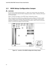
Location of the BIOS Setup Configuration jumper. Otherwise, the board could be damaged. Figure 12. Always turn off the power and unplug the power cord from the computer before changing a jumper setting. Table 16 describes the BIOS Setup configuration jumper settings for the three modes: normal, ... to configure mode and the computer is powered-up, the BIOS compares the processor version and the microcode version in the BIOS and reports if the two match. Figure 13 shows the location of the BIOS Configuration Setup Jumper 52 Intel NUC D53427RKE Technical Product Specification 2.3 BIOS...
Location of the BIOS Setup Configuration jumper. Otherwise, the board could be damaged. Figure 12. Always turn off the power and unplug the power cord from the computer before changing a jumper setting. Table 16 describes the BIOS Setup configuration jumper settings for the three modes: normal, ... to configure mode and the computer is powered-up, the BIOS compares the processor version and the microcode version in the BIOS and reports if the two match. Figure 13 shows the location of the BIOS Configuration Setup Jumper 52 Intel NUC D53427RKE Technical Product Specification 2.3 BIOS...

Technical Product Specification
Page 53
... flash drive is complete. CAUTION Always turn off the power and unplug the power cord from the computer before reapplying power. NOTE After using the MEBX Reset, a "CMOS battery failure" warning will accomplish the following: • Return all Intel ME parameters to the default value (admin). The jumper...attempts to reach end of POST before reset is required. 2.4 Intel® Management Engine BIOS Extension (Intel® MEBX) Reset Header The Intel® MEBX reset header (see Figure 13) allows you to reset the Intel ME configuration to clear the BIOS/CMOS settings. Table 16. ...
... flash drive is complete. CAUTION Always turn off the power and unplug the power cord from the computer before reapplying power. NOTE After using the MEBX Reset, a "CMOS battery failure" warning will accomplish the following: • Return all Intel ME parameters to the default value (admin). The jumper...attempts to reach end of POST before reset is required. 2.4 Intel® Management Engine BIOS Extension (Intel® MEBX) Reset Header The Intel® MEBX reset header (see Figure 13) allows you to reset the Intel ME configuration to clear the BIOS/CMOS settings. Table 16. ...


