
Technical Product Specification
Page 8
... Reference 2.1 Memory Resources 41 2.1.1 Addressable Memory 41 2.2 Connectors and Headers 42 2.2.1 Back Panel Connectors 43 2.2.2 Connectors and Headers (Bottom 44 2.3 BIOS Setup Configuration Jumper 52 2.4 Intel® Management Engine BIOS Extension (Intel® MEBX) Reset Header . 53 2.5 Mechanical Considerations 55 2.5.1 Form Factor 55 2.6 Electrical Considerations 56 2.6.1 Power Supply Considerations 56 2.6.2 Fan Header Current Capability 57...
... Reference 2.1 Memory Resources 41 2.1.1 Addressable Memory 41 2.2 Connectors and Headers 42 2.2.1 Back Panel Connectors 43 2.2.2 Connectors and Headers (Bottom 44 2.3 BIOS Setup Configuration Jumper 52 2.4 Intel® Management Engine BIOS Extension (Intel® MEBX) Reset Header . 53 2.5 Mechanical Considerations 55 2.5.1 Form Factor 55 2.6 Electrical Considerations 56 2.6.1 Power Supply Considerations 56 2.6.2 Fan Header Current Capability 57...

Technical Product Specification
Page 9
...Connectors and Headers (Bottom 44 10. Feature Summary 11 2. Supported Memory Configurations 19 5. PCI Express Full-/Half-Mini Card Connector 46 12. Intel MEBX Reset Header Signals 54 18. Thermal Solution and Fan Header 30 7. Board Dimensions 55 15. Components Shown in Figure 2 16 4. Wake-up ... Specifications 60 22. Localized High Temperature Zones 58 16. Block Diagram 17 4. Effects of the Standby Power LED 35 8. Location of the BIOS Configuration Setup Jumper 52 13. Dual-Port Front Panel USB 2.0 Header 48 13. 19 V Internal Power Supply Connector 49 14. Major Board...
...Connectors and Headers (Bottom 44 10. Feature Summary 11 2. Supported Memory Configurations 19 5. PCI Express Full-/Half-Mini Card Connector 46 12. Intel MEBX Reset Header Signals 54 18. Thermal Solution and Fan Header 30 7. Board Dimensions 55 15. Components Shown in Figure 2 16 4. Wake-up ... Specifications 60 22. Localized High Temperature Zones 58 16. Block Diagram 17 4. Effects of the Standby Power LED 35 8. Location of the BIOS Configuration Setup Jumper 52 13. Dual-Port Front Panel USB 2.0 Header 48 13. 19 V Internal Power Supply Connector 49 14. Major Board...
Technical Product Specification
Page 26
NOTE If the battery and AC power fail, date and time values will be reset and the user will be accurate. Figure 1 on page 13 shows the location of the battery. 1.8 LAN Subsystem The LAN subsystem consists of the LAN ... with an equivalent one. The clock is accurate to http://downloadcenter.intel.com 26 When the voltage drops below a certain level, the BIOS Setup program settings stored in , the standby current from the power supply extends the life of three years. Intel NUC D53427RKE Technical Product Specification 1.7 Real-Time Clock Subsystem A coin-cell...
NOTE If the battery and AC power fail, date and time values will be reset and the user will be accurate. Figure 1 on page 13 shows the location of the battery. 1.8 LAN Subsystem The LAN subsystem consists of the LAN ... with an equivalent one. The clock is accurate to http://downloadcenter.intel.com 26 When the voltage drops below a certain level, the BIOS Setup program settings stored in , the standby current from the power supply extends the life of three years. Intel NUC D53427RKE Technical Product Specification 1.7 Real-Time Clock Subsystem A coin-cell...
Technical Product Specification
Page 50
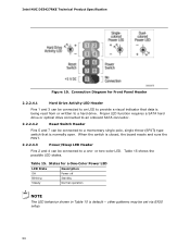
... that is normally open. States for Front Panel Header 2.2.2.4.1 Hard Drive Activity LED Header Pins 1 and 3 can be set via BIOS setup. 50 or two-color LED. Proper LED function requires a SATA hard drive or optical drive connected to an onboard SATA connector... be connected to a one- When the switch is closed, the board resets and runs the POST. 2.2.2.4.3 Power/Sleep LED Header Pins 2 and 4 can be connected to a momentary single pole, single throw (SPST) type switch that data is default - Table 15. Intel NUC D53427RKE Technical Product Specification Figure 10.
... that is normally open. States for Front Panel Header 2.2.2.4.1 Hard Drive Activity LED Header Pins 1 and 3 can be set via BIOS setup. 50 or two-color LED. Proper LED function requires a SATA hard drive or optical drive connected to an onboard SATA connector... be connected to a one- When the switch is closed, the board resets and runs the POST. 2.2.2.4.3 Power/Sleep LED Header Pins 2 and 4 can be connected to a momentary single pole, single throw (SPST) type switch that data is default - Table 15. Intel NUC D53427RKE Technical Product Specification Figure 10.

Technical Product Specification
Page 53
... Function/Mode Normal Configure Jumper Setting 1-2 2-3 Configuration The BIOS uses current configuration information and passwords for the jumper. A recovery CD or flash drive is required. 2.4 Intel® Management Engine BIOS Extension (Intel® MEBX) Reset Header The Intel® MEBX reset header (see Figure 13) allows you to reset the Intel ME configuration to the default value (admin). Technical...
... Function/Mode Normal Configure Jumper Setting 1-2 2-3 Configuration The BIOS uses current configuration information and passwords for the jumper. A recovery CD or flash drive is required. 2.4 Intel® Management Engine BIOS Extension (Intel® MEBX) Reset Header The Intel® MEBX reset header (see Figure 13) allows you to reset the Intel ME configuration to the default value (admin). Technical...
Technical Product Specification
Page 69
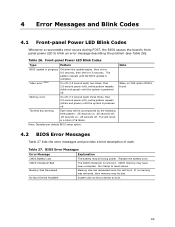
...a total of each ) three times, then 2.5-second pause (off . Note: Disabled per default BIOS setup option. Memory Size Decreased Memory size has decreased since the last boot. Run Setup to reset values. CMOS memory may be accompanied by the following blink pattern: .25 seconds on, .25 seconds... off, .25 seconds on for 0.5 seconds, then off . Table 26. Table 27. Memory error On-off . This will be losing power. BIOS Error Messages Error Message...
...a total of each ) three times, then 2.5-second pause (off . Note: Disabled per default BIOS setup option. Memory Size Decreased Memory size has decreased since the last boot. Run Setup to reset values. CMOS memory may be accompanied by the following blink pattern: .25 seconds on, .25 seconds... off, .25 seconds on for 0.5 seconds, then off . Table 26. Table 27. Memory error On-off . This will be losing power. BIOS Error Messages Error Message...


