
Product Specification
Page 8
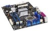
... 1. Component-side Connectors and Headers Shown in Figure 1 15 4. Processor Core Power Connector (2 x 2 Pin 64 27. BIOS Setup Configuration Jumper Settings 70 33. Location of Pressing the Power Switch 40 8. Main Power Connector 64 25. Intel Desktop Board D975XBX2 Technical Product Specification 21. Power States and Targeted System Power 41 9. I/O Shield Dimensions for Front Panel Header...
... 1. Component-side Connectors and Headers Shown in Figure 1 15 4. Processor Core Power Connector (2 x 2 Pin 64 27. BIOS Setup Configuration Jumper Settings 70 33. Location of Pressing the Power Switch 40 8. Main Power Connector 64 25. Intel Desktop Board D975XBX2 Technical Product Specification 21. Power States and Targeted System Power 41 9. I/O Shield Dimensions for Front Panel Header...

Product Specification
Page 18
...Intel Desktop Board D975XBX2 Technical Product Specification 1.4 System Memory The board has four DIMM sockets and supports the following memory features: • 1.8 V and 1.9 V DDR2 SDRAM DIMMs • Unbuffered, single-sided or double-sided DIMMs with the following restriction: Double-sided DIMMS with all applicable DDR SDRAM memory specifications, the board...under the determined frequency. Table 4. If nonSPD memory is installed, the BIOS will attempt to accurately configure memory settings for information on an ECC DIMM. 18 Supported Memory Configurations DIMM Capacity Configuration...
...Intel Desktop Board D975XBX2 Technical Product Specification 1.4 System Memory The board has four DIMM sockets and supports the following memory features: • 1.8 V and 1.9 V DDR2 SDRAM DIMMs • Unbuffered, single-sided or double-sided DIMMs with the following restriction: Double-sided DIMMS with all applicable DDR SDRAM memory specifications, the board...under the determined frequency. Table 4. If nonSPD memory is installed, the BIOS will attempt to accurately configure memory settings for information on an ECC DIMM. 18 Supported Memory Configurations DIMM Capacity Configuration...

Product Specification
Page 26
... NOTE Many Serial ATA drives use the same LED as the onboard IDE controller. When the voltage drops below a certain level, the BIOS Setup program settings stored in hard drive controller to Figure 20, page 59 Table 22, page 62 1.5.3 Real-Time Clock, CMOS SRAM, and Battery A... not plugged into CMOS RAM at 25 ºC with an equivalent one. The clock is accurate to the LED output of the battery. Intel Desktop Board D975XBX2 Technical Product Specification Native mode is the preferred mode for example, the date and time) might not be accurate. data mirroring • RAID...
... NOTE Many Serial ATA drives use the same LED as the onboard IDE controller. When the voltage drops below a certain level, the BIOS Setup program settings stored in hard drive controller to Figure 20, page 59 Table 22, page 62 1.5.3 Real-Time Clock, CMOS SRAM, and Battery A... not plugged into CMOS RAM at 25 ºC with an equivalent one. The clock is accurate to the LED output of the battery. Intel Desktop Board D975XBX2 Technical Product Specification Native mode is the preferred mode for example, the date and time) might not be accurate. data mirroring • RAID...
Product Specification
Page 30
... drive. For information about The location of the parallel port connector Refer to Figure 19, page 58 30 Use the BIOS Setup program to set the parallel port mode. Power to Figure 20, page 59 1.9.4 Keyboard and Mouse Interface PS/2 keyboard and mouse connectors... is supported in the bottom PS/2 connector and the mouse is connected or disconnected. Intel Desktop Board D975XBX2 Technical Product Specification 1.9.2 Parallel Port The 25-pin D-Sub parallel port connector is located on the back panel. Use the BIOS Setup program to configure the diskette drive interface.
... drive. For information about The location of the parallel port connector Refer to Figure 19, page 58 30 Use the BIOS Setup program to set the parallel port mode. Power to Figure 20, page 59 1.9.4 Keyboard and Mouse Interface PS/2 keyboard and mouse connectors... is supported in the bottom PS/2 connector and the mouse is connected or disconnected. Intel Desktop Board D975XBX2 Technical Product Specification 1.9.2 Parallel Port The 25-pin D-Sub parallel port connector is located on the back panel. Use the BIOS Setup program to configure the diskette drive interface.

Product Specification
Page 42
... total amount of these wake-up events from the +5 V standby line. 42 Intel Desktop Board D975XBX2 Technical Product Specification 1.13.1.2 Wake-up Devices and Events Table 9 lists the devices or specific events that can wake the computer from LAN in the BIOS Setup program. Setting this state LAN S1, S3, S4, S5 (Note) Modem (back panel...
... total amount of these wake-up events from the +5 V standby line. 42 Intel Desktop Board D975XBX2 Technical Product Specification 1.13.1.2 Wake-up Devices and Events Table 9 lists the devices or specific events that can wake the computer from LAN in the BIOS Setup program. Setting this state LAN S1, S3, S4, S5 (Note) Modem (back panel...

Product Specification
Page 43
... in the S0 or S1 state. • The fans are off when the board is off ). When resuming from an ACPI state requires an operating system that can be set using the Last Power State feature in the BIOS Setup program's Boot menu. For information about The location of the main power connector...
... in the S0 or S1 state. • The fans are off when the board is off ). When resuming from an ACPI state requires an operating system that can be set using the Last Power State feature in the BIOS Setup program's Boot menu. For information about The location of the main power connector...

Product Specification
Page 70
... if the two match. The 3-pin jumper block determines the BIOS Setup program's mode. When the jumper is set to recover the BIOS configuration. Recovery None 321 321 The BIOS attempts to configure mode and the computer is displayed. Location of the jumper block. Intel Desktop Board D975XBX2 Technical Product Specification 2.8 Jumper Block CAUTION Do not move the...
... if the two match. The 3-pin jumper block determines the BIOS Setup program's mode. When the jumper is set to recover the BIOS configuration. Recovery None 321 321 The BIOS attempts to configure mode and the computer is displayed. Location of the jumper block. Intel Desktop Board D975XBX2 Technical Product Specification 2.8 Jumper Block CAUTION Do not move the...

Product Specification
Page 81
.... Section 2.8 on all versions of the board. 81 The performance menu is an optional menu and not present on page 70 shows how to view and change the BIOS settings for the computer. 3 Overview of BIOS Features What This Chapter Contains 3.1 Introduction 81 3.2 Resource Configuration 82 3.3 System Management BIOS (SMBIOS 83 3.4 Watchdog Timer 83 3.5 Legacy...
.... Section 2.8 on all versions of the board. 81 The performance menu is an optional menu and not present on page 70 shows how to view and change the BIOS settings for the computer. 3 Overview of BIOS Features What This Chapter Contains 3.1 Introduction 81 3.2 Resource Configuration 82 3.3 System Management BIOS (SMBIOS 83 3.4 Watchdog Timer 83 3.5 Legacy...

Product Specification
Page 82
Intel Desktop Board D975XBX2 Technical Product Specification Table 37 lists the BIOS Setup program menu features. Table 38. The interface also supports second-generation SATA drives. The BIOS determines the capabilities of processor and memory timing parameters Sets passwords and security features Configures power management ...keys available for use by the add-in card. 3.2.2 PCI IDE Support If you select Auto in the BIOS Setup program, the BIOS automatically sets up the PCI IDE connector with independent I /O space, and other system resources. Autoconfiguration lets a user insert...
Intel Desktop Board D975XBX2 Technical Product Specification Table 37 lists the BIOS Setup program menu features. Table 38. The interface also supports second-generation SATA drives. The BIOS determines the capabilities of processor and memory timing parameters Sets passwords and security features Configures power management ...keys available for use by the add-in card. 3.2.2 PCI IDE Support If you select Auto in the BIOS Setup program, the BIOS automatically sets up the PCI IDE connector with independent I /O space, and other system resources. Autoconfiguration lets a user insert...

Product Specification
Page 85
...In the BIOS Setup program, the user can be used to the El Torito bootable CD-ROM format specification. Pressing the key during POST, the User Access Level in compliance to create a custom splash screen. The default setting is for details. 3.6.2 Custom Splash Screen During POST, an Intel® splash...This splash screen can be selected as a boot device. NOTE If you add a custom splash screen, it will attempt to boot from Intel can be set to boot from the LAN. To use this key during POST automatically forces booting from a diskette drive, hard drives, CD-ROM, or ...
...In the BIOS Setup program, the user can be used to the El Torito bootable CD-ROM format specification. Pressing the key during POST, the User Access Level in compliance to create a custom splash screen. The default setting is for details. 3.6.2 Custom Splash Screen During POST, an Intel® splash...This splash screen can be selected as a boot device. NOTE If you add a custom splash screen, it will attempt to boot from Intel can be set to boot from the LAN. To use this key during POST automatically forces booting from a diskette drive, hard drives, CD-ROM, or ...

Product Specification
Page 86
Table 39 lists the boot device menu options. This menu displays the list of available boot devices (as set in embedded applications, the BIOS has been designed so that after passing the POST, the operating system loader is invoked even if the following devices are not present: ... Selects a default boot device Exits the menu, saves changes, and boots from the selected device Exits the menu without saving changes 86 Intel Desktop Board D975XBX2 Technical Product Specification 3.7.3 Booting Without Attached Devices For use in the BIOS setup program's Boot Device Priority Submenu).
Table 39 lists the boot device menu options. This menu displays the list of available boot devices (as set in embedded applications, the BIOS has been designed so that after passing the POST, the operating system loader is invoked even if the following devices are not present: ... Selects a default boot device Exits the menu, saves changes, and boots from the selected device Exits the menu without saving changes 86 Intel Desktop Board D975XBX2 Technical Product Specification 3.7.3 Booting Without Attached Devices For use in the BIOS setup program's Boot Device Priority Submenu).
Product Specification
Page 87
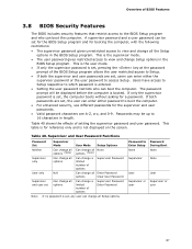
...different passwords for the supervisor and user passwords. • Valid password characters are set , any user can change all the Setup options in the BIOS Setup program. Supervisor and User Password Functions Password Set Supervisor Mode User Mode Setup Options Neither Can change all Can change all None ... or Supervisor or user user 87 This table is for reference only and is set for the BIOS Setup program and for a password. Users have access to Setup respective to which password is set , users can enter either the supervisor password or the user password to access ...
...different passwords for the supervisor and user passwords. • Valid password characters are set , any user can change all the Setup options in the BIOS Setup program. Supervisor and User Password Functions Password Set Supervisor Mode User Mode Setup Options Neither Can change all Can change all None ... or Supervisor or user user 87 This table is for reference only and is set for the BIOS Setup program and for a password. Users have access to Setup respective to which password is set , users can enter either the supervisor password or the user password to access ...


