Product Specification
Page 2
... BY THIS DOCUMENT. may be supported without further evaluation by estoppel or otherwise, to only the standard Intel® Desktop Board D975XBX2 with BIOS identifier BX97520J.86A. Intel may be published in homes, offices, schools, computer rooms, and similar locations. Contact your local Intel sales office or your distributor to deviate from published specifications. All rights reserved...
... BY THIS DOCUMENT. may be supported without further evaluation by estoppel or otherwise, to only the standard Intel® Desktop Board D975XBX2 with BIOS identifier BX97520J.86A. Intel may be published in homes, offices, schools, computer rooms, and similar locations. Contact your local Intel sales office or your distributor to deviate from published specifications. All rights reserved...

Product Specification
Page 3
... and abbreviations appear in this specification. Intended Audience The TPS is specifically not intended for the Intel® Desktop Board D975XBX2. iii Preface This Technical Product Specification (TPS) specifies the board layout, components, connectors, power and environmental requirements, and the BIOS for general audiences. It describes the standard product and available manufacturing options. What This Document...
... and abbreviations appear in this specification. Intended Audience The TPS is specifically not intended for the Intel® Desktop Board D975XBX2. iii Preface This Technical Product Specification (TPS) specifies the board layout, components, connectors, power and environmental requirements, and the BIOS for general audiences. It describes the standard product and available manufacturing options. What This Document...

Product Specification
Page 6
Intel Desktop Board D975XBX2 Technical Product Specification 1.13 Power Management 39 1.13.1 ACPI 39 1.13.2 Hardware Support 42 1.14 Onboard Power Button 46 1.15 Onboard LEDs 47 1.16 ... Supply Considerations 75 2.11 Thermal Considerations 76 2.12 Reliability 78 2.13 Environmental 79 3 Overview of BIOS Features 3.1 Introduction 81 3.2 Resource Configuration 82 3.2.1 PCI Autoconfiguration 82 3.2.2 PCI IDE Support 82 3.3 System Management BIOS (SMBIOS 83 3.4 Watchdog Timer 83 3.5 Legacy USB Support 84 3.6 BIOS Updates 84 3.6.1 Language Support 85 3.6.2 Custom Splash Screen 85 vi
Intel Desktop Board D975XBX2 Technical Product Specification 1.13 Power Management 39 1.13.1 ACPI 39 1.13.2 Hardware Support 42 1.14 Onboard Power Button 46 1.15 Onboard LEDs 47 1.16 ... Supply Considerations 75 2.11 Thermal Considerations 76 2.12 Reliability 78 2.13 Environmental 79 3 Overview of BIOS Features 3.1 Introduction 81 3.2 Resource Configuration 82 3.2.1 PCI Autoconfiguration 82 3.2.2 PCI IDE Support 82 3.3 System Management BIOS (SMBIOS 83 3.4 Watchdog Timer 83 3.5 Legacy USB Support 84 3.6 BIOS Updates 84 3.6.1 Language Support 85 3.6.2 Custom Splash Screen 85 vi
Product Specification
Page 7
... Diagram 16 3. Dual Channel (Interleaved) Mode Configuration with Two DIMMs 21 5. Location of the Onboard Power Button 46 16. Desktop Board Components 14 2. Detailed System Memory Address Map 50 18. Dual Channel (Interleaved) Mode Configuration with Four DIMMs 22 7. Back ... Booting Without Attached Devices 86 3.7.4 Changing the Default Boot Device During POST 86 3.8 BIOS Security Features 87 4 Error Messages and Beep Codes 4.1 Speaker 89 4.2 BIOS Beep Codes 89 4.3 BIOS Error Messages 89 4.4 Port 80h POST Codes 90 5 Regulatory Compliance and Battery Disposal Information...
... Diagram 16 3. Dual Channel (Interleaved) Mode Configuration with Two DIMMs 21 5. Location of the Onboard Power Button 46 16. Desktop Board Components 14 2. Detailed System Memory Address Map 50 18. Dual Channel (Interleaved) Mode Configuration with Four DIMMs 22 7. Back ... Booting Without Attached Devices 86 3.7.4 Changing the Default Boot Device During POST 86 3.8 BIOS Security Features 87 4 Error Messages and Beep Codes 4.1 Speaker 89 4.2 BIOS Beep Codes 89 4.3 BIOS Error Messages 89 4.4 Port 80h POST Codes 90 5 Regulatory Compliance and Battery Disposal Information...

Product Specification
Page 8
Board Dimensions 71 26. Manufacturing Options 13 3. Memory Operating Frequencies 19 6. Wake-up Devices and Events 42 10. Main Power Connector 64 25. BIOS Setup Configuration Jumper Settings 70 33. Connection Diagram for Front Panel Header 66 22. Location of... 66 30. DC Loading Characteristics 74 viii States for Boards with the 8-Channel (7.1) Audio Subsystem 72 27. Connection Diagram for a One-Color Power LED 67 31. States for Front Panel USB Headers 68 23. Intel Desktop Board D975XBX2 Technical Product Specification 21. Feature Summary 12 2. LAN ...
Board Dimensions 71 26. Manufacturing Options 13 3. Memory Operating Frequencies 19 6. Wake-up Devices and Events 42 10. Main Power Connector 64 25. BIOS Setup Configuration Jumper Settings 70 33. Connection Diagram for Front Panel Header 66 22. Location of... 66 30. DC Loading Characteristics 74 viii States for Boards with the 8-Channel (7.1) Audio Subsystem 72 27. Connection Diagram for a One-Color Power LED 67 31. States for Front Panel USB Headers 68 23. Intel Desktop Board D975XBX2 Technical Product Specification 21. Feature Summary 12 2. LAN ...

Product Specification
Page 9
BIOS Setup Program Function Keys 82 39. Supervisor and User Password Functions 87 41. EMC Regulations 101 49. Thermal Considerations for Components 78 36. Environmental Specifications 79 37. Port 80h POST Code Ranges 90 44. Fan Header Current Capability 75 35. Beep Codes 89 42. Typical Port 80h POST Sequence 94 46. Lead-Free Board Markings 100 48. BIOS Setup Program Menu Bar 82 38. Product Certification Markings 102 ix Contents 34. Boot Device Menu Options 86 40. BIOS Error Messages 89 43. Port 80h POST Codes 91 45. Safety Regulations 95 47.
BIOS Setup Program Function Keys 82 39. Supervisor and User Password Functions 87 41. EMC Regulations 101 49. Thermal Considerations for Components 78 36. Environmental Specifications 79 37. Port 80h POST Code Ranges 90 44. Fan Header Current Capability 75 35. Beep Codes 89 42. Typical Port 80h POST Sequence 94 46. Lead-Free Board Markings 100 48. BIOS Setup Program Menu Bar 82 38. Product Certification Markings 102 ix Contents 34. Boot Device Menu Options 86 40. BIOS Error Messages 89 43. Port 80h POST Codes 91 45. Safety Regulations 95 47.

Product Specification
Page 12
... 33, ATA-66/100 support • One diskette drive interface • PS/2* keyboard and mouse ports • Intel® BIOS resident in the SPI Flash device • Support for Advanced Configuration and Power Interface (ACPI), Plug and Play, and... 12 Table 1. Intel Desktop Board D975XBX2 Technical Product Specification 1.1 Overview 1.1.1 Feature Summary Table 1 summarizes the major features of : • Intel® 82975X Memory Controller Hub (MCH) • Intel® 82801GR I/O Controller Hub (ICH7-R) or Intel® 82801GH I/O Controller Hub (ICH7-DH) Intel® High Definition...
... 33, ATA-66/100 support • One diskette drive interface • PS/2* keyboard and mouse ports • Intel® BIOS resident in the SPI Flash device • Support for Advanced Configuration and Power Interface (ACPI), Plug and Play, and... 12 Table 1. Intel Desktop Board D975XBX2 Technical Product Specification 1.1 Overview 1.1.1 Feature Summary Table 1 summarizes the major features of : • Intel® 82975X Memory Controller Hub (MCH) • Intel® 82801GR I/O Controller Hub (ICH7-R) or Intel® 82801GH I/O Controller Hub (ICH7-DH) Intel® High Definition...

Product Specification
Page 13
... use the same LED as the onboard IDE controller A component that enhances platform security 13 Table 2. Boards equipped with a dual-rail 2 x 4 power cable). Manufacturing Options AMT ATAPI CD-ROM Connector BIOS support for Intel® Active Management Technology (Intel® AMT) A 1 x 4-pin ATAPI-style connector for connecting an internal ATAPI CD-ROM drive to...
... use the same LED as the onboard IDE controller A component that enhances platform security 13 Table 2. Boards equipped with a dual-rail 2 x 4 power cable). Manufacturing Options AMT ATAPI CD-ROM Connector BIOS support for Intel® Active Management Technology (Intel® AMT) A 1 x 4-pin ATAPI-style connector for connecting an internal ATAPI CD-ROM drive to...

Product Specification
Page 15
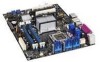
... PCI Conventional bus add-in card connector 1 Secondary PCI Express x16 (electrical x8) bus add-in card connector Front panel audio header Intel® 82801G I/O Controller Hub (ICH7-R or ICH7-DH) Primary PCI Express x16 (electrical x16 or x8) bus add-in card ... power connector Memory Controller Hub (MCH) fan header (optional) LGA775 processor socket Intel 82975X MCH DIMM Channel A sockets [2] Processor fan header DIMM Channel B sockets [2] Main power connector Diskette drive connector BIOS Setup configuration jumper block Chassis intrusion header Onboard power button Battery Parallel ATE IDE ...
... PCI Conventional bus add-in card connector 1 Secondary PCI Express x16 (electrical x8) bus add-in card connector Front panel audio header Intel® 82801G I/O Controller Hub (ICH7-R or ICH7-DH) Primary PCI Express x16 (electrical x16 or x8) bus add-in card ... power connector Memory Controller Hub (MCH) fan header (optional) LGA775 processor socket Intel 82975X MCH DIMM Channel A sockets [2] Processor fan header DIMM Channel B sockets [2] Main power connector Diskette drive connector BIOS Setup configuration jumper block Chassis intrusion header Onboard power button Battery Parallel ATE IDE ...

Product Specification
Page 18
... This allows the BIOS to read the SPD data and program the chipset to accurately configure memory settings for information on the total amount of SDRAM devices on page 49 for optimum performance. Intel Desktop Board D975XBX2 Technical Product Specification 1.4 System Memory The board has four DIMM ... To be fully compliant with all applicable DDR SDRAM memory specifications, the board should be impacted or the DIMMs may not function under the determined frequency. If nonSPD memory is installed, the BIOS will attempt to single-sided memory modules (containing one row of SDRAM Devices...
... This allows the BIOS to read the SPD data and program the chipset to accurately configure memory settings for information on the total amount of SDRAM devices on page 49 for optimum performance. Intel Desktop Board D975XBX2 Technical Product Specification 1.4 System Memory The board has four DIMM ... To be fully compliant with all applicable DDR SDRAM memory specifications, the board should be impacted or the DIMMs may not function under the determined frequency. If nonSPD memory is installed, the BIOS will attempt to single-sided memory modules (containing one row of SDRAM Devices...

Product Specification
Page 24
...routed to two separate front panel USB headers NOTES Computer systems that meets the requirements for full-speed devices. The BIOS code is attached to the cable. The ICH7-R/ICH7-DH provides the USB controller for the system bus, the ...panel The location of the following: ⎯ Intel 82801GR I/O Controller Hub (ICH7-R) with DMI interconnect ⎯ Intel 82801GH I /O paths. Intel Desktop Board D975XBX2 Technical Product Specification 1.5 Intel® 975X Chipset The Intel 975X chipset consists of the following devices: • Intel 82975X Memory Controller Hub (MCH) with Direct Media...
...routed to two separate front panel USB headers NOTES Computer systems that meets the requirements for full-speed devices. The BIOS code is attached to the cable. The ICH7-R/ICH7-DH provides the USB controller for the system bus, the ...panel The location of the following: ⎯ Intel 82801GR I/O Controller Hub (ICH7-R) with DMI interconnect ⎯ Intel 82801GH I /O paths. Intel Desktop Board D975XBX2 Technical Product Specification 1.5 Intel® 975X Chipset The Intel 975X chipset consists of the following devices: • Intel 82975X Memory Controller Hub (MCH) with Direct Media...

Product Specification
Page 25
...and write transfer rates up to 33 MB/sec. • ATA-66: DMA protocol on IDE bus allows host and target throttling. The BIOS supports Logical Block Addressing (LBA) and Extended Cylinder Head Sector (ECHS) translation modes. In Native mode, standard PCI Conventional bus resource steering... transfer rates of four Serial ATA devices. A point-to-point interface is used for a maximum of up to the BIOS. Product Description 1.5.2 IDE Support The board provides five IDE interface connectors: • One parallel ATA IDE connector that supports two devices • Four serial ATA ...
...and write transfer rates up to 33 MB/sec. • ATA-66: DMA protocol on IDE bus allows host and target throttling. The BIOS supports Logical Block Addressing (LBA) and Extended Cylinder Head Sector (ECHS) translation modes. In Native mode, standard PCI Conventional bus resource steering... transfer rates of four Serial ATA devices. A point-to-point interface is used for a maximum of up to the BIOS. Product Description 1.5.2 IDE Support The board provides five IDE interface connectors: • One parallel ATA IDE connector that supports two devices • Four serial ATA ...

Product Specification
Page 26
... activity LED header Refer to use new low-voltage power connectors and require adaptors or power supplies equipped with low-voltage power connectors. Intel Desktop Board D975XBX2 Technical Product Specification Native mode is plugged in, the standby current from , or written to ± 13 minutes/year at power-... RAID The ICH7-R/ICH7-DH supports the following RAID (Redundant Array of the battery. 26 When the voltage drops below a certain level, the BIOS Setup program settings stored in hard drive controller to Figure 20, page 59 Table 22, page 62 1.5.3 Real-Time Clock, CMOS SRAM, and...
... activity LED header Refer to use new low-voltage power connectors and require adaptors or power supplies equipped with low-voltage power connectors. Intel Desktop Board D975XBX2 Technical Product Specification Native mode is plugged in, the standby current from , or written to ± 13 minutes/year at power-... RAID The ICH7-R/ICH7-DH supports the following RAID (Redundant Array of the battery. 26 When the voltage drops below a certain level, the BIOS Setup program settings stored in hard drive controller to Figure 20, page 59 Table 22, page 62 1.5.3 Real-Time Clock, CMOS SRAM, and...

Product Specification
Page 29
... Connectors (Optional) The optional IEEE-1394 interface addresses interconnection of both asynchronous and isochronous data transfer As a manufacturing option, the board includes two IEEE-1394a connectors as follows: • One IEEE-1394a connector located on the back panel. • One IEEE... drive • Intelligent power management, including a programmable wake-up event interface • PCI Conventional bus power management support The BIOS Setup program provides configuration options for the legacy I /O controller provides the following features: • One serial port • ...
... Connectors (Optional) The optional IEEE-1394 interface addresses interconnection of both asynchronous and isochronous data transfer As a manufacturing option, the board includes two IEEE-1394a connectors as follows: • One IEEE-1394a connector located on the back panel. • One IEEE... drive • Intelligent power management, including a programmable wake-up event interface • PCI Conventional bus power management support The BIOS Setup program provides configuration options for the legacy I /O controller provides the following features: • One serial port • ...
Product Specification
Page 30
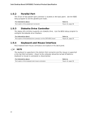
...top PS/2 connector. For information about The location of the keyboard and mouse connectors Refer to configure the diskette drive interface. Intel Desktop Board D975XBX2 Technical Product Specification 1.9.2 Parallel Port The 25-pin D-Sub parallel port connector is located on the back panel. For information ...about The location of the diskette drive connector on the D975XBX2 board Refer to Figure 19, page 58 1.9.3 Diskette Drive Controller The legacy I/O controller supports one diskette drive. Use the BIOS Setup program to Figure 19, page 58 30 Power to set the...
...top PS/2 connector. For information about The location of the keyboard and mouse connectors Refer to configure the diskette drive interface. Intel Desktop Board D975XBX2 Technical Product Specification 1.9.2 Parallel Port The 25-pin D-Sub parallel port connector is located on the back panel. For information ...about The location of the diskette drive connector on the D975XBX2 board Refer to Figure 19, page 58 1.9.3 Diskette Drive Controller The legacy I/O controller supports one diskette drive. Use the BIOS Setup program to Figure 19, page 58 30 Power to set the...

Product Specification
Page 35
Product Description 1.11.3 Alert Standard Format (ASF) Support The board provides the following ASF support for networked platforms. With Intel AMT, IT organizations can easily get accurate platform information, and can perform remote updating, diagnostics, debugging and ...bus add-in LAN cards and PCI Conventional bus add-in LAN cards: • Monitoring of system firmware progress events, including: ⎯ BIOS present ⎯ Primary processor initialization ⎯ Memory initialization ⎯ Video initialization ⎯ PCI resource configuration ⎯ Hard-disk initialization ⎯...
Product Description 1.11.3 Alert Standard Format (ASF) Support The board provides the following ASF support for networked platforms. With Intel AMT, IT organizations can easily get accurate platform information, and can perform remote updating, diagnostics, debugging and ...bus add-in LAN cards and PCI Conventional bus add-in LAN cards: • Monitoring of system firmware progress events, including: ⎯ BIOS present ⎯ Primary processor initialization ⎯ Memory initialization ⎯ Video initialization ⎯ PCI resource configuration ⎯ Hard-disk initialization ⎯...
Product Specification
Page 36
Network drive or remote CD boot ⎯ Serial over LAN ⎯ OOB diagnostics ⎯ Remote control ⎯ Remote BIOS update • Proactive alerting that decreases downtime and minimizes time to repair: ⎯ Programmable policies ⎯ Operating system lock...9135; Nonvolatile storage for access anytime by third party software to check and, if necessary, wake a system to http://www.intel.com/technology/manage/iamt/index.htm 36 Intel Desktop Board D975XBX2 Technical Product Specification • Healing systems remotely, regardless of the operating system or system state: ⎯...
Network drive or remote CD boot ⎯ Serial over LAN ⎯ OOB diagnostics ⎯ Remote control ⎯ Remote BIOS update • Proactive alerting that decreases downtime and minimizes time to repair: ⎯ Programmable policies ⎯ Operating system lock...9135; Nonvolatile storage for access anytime by third party software to check and, if necessary, wake a system to http://www.intel.com/technology/manage/iamt/index.htm 36 Intel Desktop Board D975XBX2 Technical Product Specification • Healing systems remotely, regardless of the operating system or system state: ⎯...

Product Specification
Page 42
...up support • WAKE# signal wake-up support LAN wake capabilities and Instantly Available PC technology require power from LAN in the BIOS Setup program. The total amount of these wake-up events from an ACPI state requires an operating system that can wake the ... wake up the computer... ...from specific states. Failure to Power On will enable a wake-up event from the +5 V standby line. 42 Intel Desktop Board D975XBX2 Technical Product Specification 1.13.1.2 Wake-up Devices and Events Table 9 lists the devices or specific events that provides full ACPI support. Table 9. In...
...up support • WAKE# signal wake-up support LAN wake capabilities and Instantly Available PC technology require power from LAN in the BIOS Setup program. The total amount of these wake-up events from an ACPI state requires an operating system that can wake the ... wake up the computer... ...from specific states. Failure to Power On will enable a wake-up event from the +5 V standby line. 42 Intel Desktop Board D975XBX2 Technical Product Specification 1.13.1.2 Wake-up Devices and Events Table 9 lists the devices or specific events that provides full ACPI support. Table 9. In...

Product Specification
Page 43
When resuming from an ACPI state requires an operating system that can be set using the Last Power State feature in the BIOS Setup program's Boot menu. For information about The location of the main power connector The signal names of the main power connector Refer to Figure ... fan speed or switch the fan on or off as follows: • The fans are on when the board is in the S0 or S1 state. • The fans are off when the board is off or in the S3, S4, or S5 state. • Each fan header is in before power...
When resuming from an ACPI state requires an operating system that can be set using the Last Power State feature in the BIOS Setup program's Boot menu. For information about The location of the main power connector The signal names of the main power connector Refer to Figure ... fan speed or switch the fan on or off as follows: • The fans are on when the board is in the S0 or S1 state. • The fans are off when the board is off or in the S3, S4, or S5 state. • Each fan header is in before power...

Product Specification
Page 45
... and the standby power indicator is still lit, disconnect the power cord before installing or removing any devices connected to do so could damage the board and any attached devices. NOTE Wake from USB requires the use of a USB peripheral that supports Wake from USB. 1.13.2.7 Wake from PS/2 ..., the computer wakes from an ACPI S1, S3, S4, or S5 state (with Wake on PME enabled in the BIOS). 1.13.2.9 WAKE# Signal Wake-up Support When the WAKE# signal on the D975XBX2 board. Failure to the board. OM18534 Figure 14. Figure 14 shows the location of the Standby Power Indicator LED 45
... and the standby power indicator is still lit, disconnect the power cord before installing or removing any devices connected to do so could damage the board and any attached devices. NOTE Wake from USB requires the use of a USB peripheral that supports Wake from USB. 1.13.2.7 Wake from PS/2 ..., the computer wakes from an ACPI S1, S3, S4, or S5 state (with Wake on PME enabled in the BIOS). 1.13.2.9 WAKE# Signal Wake-up Support When the WAKE# signal on the D975XBX2 board. Failure to the board. OM18534 Figure 14. Figure 14 shows the location of the Standby Power Indicator LED 45


