
Product Guide
Page 6
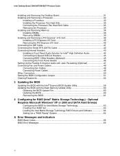
... Microsoft Windows* XP or 2000 and SATA Hard Drive(s) Configuring the BIOS for RAID (Intel® Matrix Storage Technology) - Intel Desktop Board D945GNT/D945GTP Product Guide Installing and Removing the Desktop Board 31 Installing and Removing a Processor 32 Installing...Panel Header 46 Setting Up the Flexible 6-Channel Audio with Jack Re-tasking (Optional 47 Connecting Fan and Power Cables 48 Connecting Fan Cables 48 Connecting Power Cables 49 Other Connectors...50 Setting the BIOS Configuration Jumper 51 Clearing Passwords ...52 3 Updating the BIOS Updating the BIOS with the Intel...
... Microsoft Windows* XP or 2000 and SATA Hard Drive(s) Configuring the BIOS for RAID (Intel® Matrix Storage Technology) - Intel Desktop Board D945GNT/D945GTP Product Guide Installing and Removing the Desktop Board 31 Installing and Removing a Processor 32 Installing...Panel Header 46 Setting Up the Flexible 6-Channel Audio with Jack Re-tasking (Optional 47 Connecting Fan and Power Cables 48 Connecting Fan Cables 48 Connecting Power Cables 49 Other Connectors...50 Setting the BIOS Configuration Jumper 51 Clearing Passwords ...52 3 Updating the BIOS Updating the BIOS with the Intel...

Product Guide
Page 7
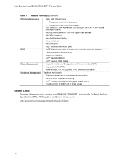
... Certification Markings (Board Level 74 Figures 1. Contents B Regulatory Compliance Safety Regulations ...67 European Union Declaration of Other Connectors on Desktop Board D945GNT/D945GTP 50 26. Install Processor ...34 12. Connecting the Serial ATA Cable 42 21. Connecting 2x12 Power Supply Cables ... Processor Cover/Do Not Touch 33 11. Back Panel Audio Connectors for Flexible 6-Channel Audio System 47 23. Removing the Battery 57 28. Installing the I/O Shield 30 6. Close the Load Plate ...34 13. Intel Desktop Board D945GTP Components 14 3. LAN Port LED Locations 20 4....
... Certification Markings (Board Level 74 Figures 1. Contents B Regulatory Compliance Safety Regulations ...67 European Union Declaration of Other Connectors on Desktop Board D945GNT/D945GTP 50 26. Install Processor ...34 12. Connecting the Serial ATA Cable 42 21. Connecting 2x12 Power Supply Cables ... Processor Cover/Do Not Touch 33 11. Back Panel Audio Connectors for Flexible 6-Channel Audio System 47 23. Removing the Battery 57 28. Installing the I/O Shield 30 6. Close the Load Plate ...34 13. Intel Desktop Board D945GTP Components 14 3. LAN Port LED Locations 20 4....
Product Guide
Page 10
...• One VGA connector • One diskette drive interface • One parallel port BIOS • One serial port • PS/2* keyboard and mouse ports • Intel® Platform Innovation ... LAN, and front panel Hardware Management Hardware monitor with: • Three fan sensing inputs used to monitor fan activity • Remote diode temperature sensing • Intel® Precision Cooling... Technology fan speed control • Voltage sensing to detect out of range values Related Links: For more information about desktop board D945GNT/D945GTP, ...
...• One VGA connector • One diskette drive interface • One parallel port BIOS • One serial port • PS/2* keyboard and mouse ports • Intel® Platform Innovation ... LAN, and front panel Hardware Management Hardware monitor with: • Three fan sensing inputs used to monitor fan activity • Remote diode temperature sensing • Intel® Precision Cooling... Technology fan speed control • Voltage sensing to detect out of range values Related Links: For more information about desktop board D945GNT/D945GTP, ...

Product Guide
Page 11
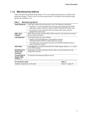
... board D945GNT/D945GTP. Manufacturing Options Option Peripheral interface Hardware management Description Up to three IEEE 1394a ports • One port routed to the back panel • Two ports routed to two IEEE 1394a headers • Intel® 82562GZ 10/100 Mbit/sec Platform LAN Connect (PLC) device with RJ-45 connector • Intel® 82573E...
... board D945GNT/D945GTP. Manufacturing Options Option Peripheral interface Hardware management Description Up to three IEEE 1394a ports • One port routed to the back panel • Two ports routed to two IEEE 1394a headers • Intel® 82562GZ 10/100 Mbit/sec Platform LAN Connect (PLC) device with RJ-45 connector • Intel® 82573E...
Product Guide
Page 13
..., fan speed control) Processor socket Processor fan header (4-pin, fan speed control) Main power connector (2x12) Diskette drive connector IDE connector Front chassis fan header (3-pin, fan speed control) BIOS configuration jumper Chassis intrusion header Serial ATA connectors Front panel header Alternate power LED header Hi-speed USB 2.0 headers IEEE 1394a headers (optional) PCI bus...
..., fan speed control) Processor socket Processor fan header (4-pin, fan speed control) Main power connector (2x12) Diskette drive connector IDE connector Front chassis fan header (3-pin, fan speed control) BIOS configuration jumper Chassis intrusion header Serial ATA connectors Front panel header Alternate power LED header Hi-speed USB 2.0 headers IEEE 1394a headers (optional) PCI bus...

Product Guide
Page 15
... panel header Alternate power LED header Hi-speed USB 2.0 headers IEEE 1394 headers (optional) PCI Express x1 connector Related Links: Go to the following links for more information about: • Desktop board D945GNT/D945GTP • Supported processors • Audio software and utilities • LAN software and drivers http://www.intel.com/design/motherbd http...
... panel header Alternate power LED header Hi-speed USB 2.0 headers IEEE 1394 headers (optional) PCI Express x1 connector Related Links: Go to the following links for more information about: • Desktop board D945GNT/D945GTP • Supported processors • Audio software and utilities • LAN software and drivers http://www.intel.com/design/motherbd http...

Product Guide
Page 18
...; S/N (signal-to the following link for more information about the Intel 945G Express Chipset: http://developer.intel.com/design/nav/pcserver.htm Graphics Subsystem Desktop board D945GNT/D945GTP includes the following connectors: • Front panel audio connector, including functionality for graphics expansion Audio Subsystem Desktop board D945GNT/D945GTP includes a flexible 6- or 8-channel audio subsystem based on an...
...; S/N (signal-to the following link for more information about the Intel 945G Express Chipset: http://developer.intel.com/design/nav/pcserver.htm Graphics Subsystem Desktop board D945GNT/D945GTP includes the following connectors: • Front panel audio connector, including functionality for graphics expansion Audio Subsystem Desktop board D945GNT/D945GTP includes a flexible 6- or 8-channel audio subsystem based on an...

Product Specification
Page 6
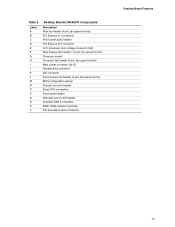
Intel Desktop Board D945GTP Technical Product Specification 2 Technical Reference 2.1 Introduction ...45 2.2 Memory Resources ...45 2.2.1 Addressable Memory 45 2.2.2 Memory Map 47 2.3 DMA Channels ...47 2.4 Fixed I/O Map...48 2.5 PCI Configuration Space Map 49 2.6 Interrupts ...50 2.7 PCI Conventional Interrupt Routing Map 51 2.8 Connectors...53 2.8.1 Back Panel Connectors 53 2.8.2 Component-side Connectors 56 2.9 Jumper Block ...65 2.10 Mechanical Considerations 66 2.10...
Intel Desktop Board D945GTP Technical Product Specification 2 Technical Reference 2.1 Introduction ...45 2.2 Memory Resources ...45 2.2.1 Addressable Memory 45 2.2.2 Memory Map 47 2.3 DMA Channels ...47 2.4 Fixed I/O Map...48 2.5 PCI Configuration Space Map 49 2.6 Interrupts ...50 2.7 PCI Conventional Interrupt Routing Map 51 2.8 Connectors...53 2.8.1 Back Panel Connectors 53 2.8.2 Component-side Connectors 56 2.9 Jumper Block ...65 2.10 Mechanical Considerations 66 2.10...

Product Specification
Page 7
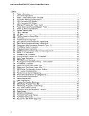
... (7.1) Audio Subsystem Block Diagram 29 11. Single Channel (Asymmetric) Mode Configuration with Three DIMMs 20 9. LAN Connector LED Locations 32 14. Component-side Connectors 56 21. Connection Diagram for Front Panel USB Connectors 64 23. Connection Diagram for Front Panel Connector 62 22. I /O Shield Dimensions for Boards with Two DIMMs 18 5. Memory Channel and DIMM Configuration...
... (7.1) Audio Subsystem Block Diagram 29 11. Single Channel (Asymmetric) Mode Configuration with Three DIMMs 20 9. LAN Connector LED Locations 32 14. Component-side Connectors 56 21. Connection Diagram for Front Panel USB Connectors 64 23. Connection Diagram for Front Panel Connector 62 22. I /O Shield Dimensions for Boards with Two DIMMs 18 5. Memory Channel and DIMM Configuration...
Product Specification
Page 8
... Setup Program Function Keys 80 41. Intel Desktop Board D945GTP Technical Product Specification Tables 1. PCI Interrupt Routing Map 51 16. Feature Summary ...10 2. Boot Device Menu Options 83 42. Processor Fan Connector 59 24. Back Panel Connectors Shown in Figure 20 57 19. Auxiliary Front Panel Power/Sleep LED Connector 61 28. Effects of Pressing the Power...
... Setup Program Function Keys 80 41. Intel Desktop Board D945GTP Technical Product Specification Tables 1. PCI Interrupt Routing Map 51 16. Feature Summary ...10 2. Boot Device Menu Options 83 42. Processor Fan Connector 59 24. Back Panel Connectors Shown in Figure 20 57 19. Auxiliary Front Panel Power/Sleep LED Connector 61 28. Effects of Pressing the Power...
Product Specification
Page 11
... audio codec IEEE-1394a Interface IEEE-1394a controller and three IEEE-1394a connectors (one back panel connector, two front-panel connectors) LAN subsystem SATA RAID The board provides one of the following: • Gigabit (10/100/1000 Mbits/sec) LAN subsystem using the Intel® 82573E/82573V/82574V Gigabit Ethernet Controller • 10/100 Mbits/sec...
... audio codec IEEE-1394a Interface IEEE-1394a controller and three IEEE-1394a connectors (one back panel connector, two front-panel connectors) LAN subsystem SATA RAID The board provides one of the following: • Gigabit (10/100/1000 Mbits/sec) LAN subsystem using the Intel® 82573E/82573V/82574V Gigabit Ethernet Controller • 10/100 Mbits/sec...

Product Specification
Page 23
...drivers. When an ADD2/ADD2+ card is detected, the Intel GMA950 graphics controller is enabled and the PCI Express x16 connector is as an extended desktop configuration with dual stacked back panel connectors adjacent to the audio connectors • Four ports are each capable of supported modes ...for the Intel GMA950 graphics controller is attached to the cable....
...drivers. When an ADD2/ADD2+ card is detected, the Intel GMA950 graphics controller is enabled and the PCI Express x16 connector is as an extended desktop configuration with dual stacked back panel connectors adjacent to the audio connectors • Four ports are each capable of supported modes ...for the Intel GMA950 graphics controller is attached to the cable....

Product Specification
Page 26
... applied. Intel Desktop Board D945GTP Technical Product Specification 1.5.4 Real-Time Clock, CMOS SRAM, and Battery A coin-cell battery (CR2032) powers the real-time clock and CMOS memory. As a manufacturing option, the board includes three IEEE-1394a connectors as follows: • One IEEE-1394a connector located on the back panel. • Two IEEE-1394a front-panel connectors located...
... applied. Intel Desktop Board D945GTP Technical Product Specification 1.5.4 Real-Time Clock, CMOS SRAM, and Battery A coin-cell battery (CR2032) powers the real-time clock and CMOS memory. As a manufacturing option, the board includes three IEEE-1394a connectors as follows: • One IEEE-1394a connector located on the back panel. • Two IEEE-1394a front-panel connectors located...

Product Specification
Page 53
... not use these groups: • Back panel I/O connectors (see page 55) • Component-side I/O connectors (see page 53) 2.8.1 Back Panel Connectors The back panel configuration is dependent upon which audio subsystem is present. This section describes the board's connectors. Technical Reference 2.8 Connectors CAUTION Only the following connectors have overcurrent protection: back panel USB, front panel USB, and PS/2. The other internal...
... not use these groups: • Back panel I/O connectors (see page 55) • Component-side I/O connectors (see page 53) 2.8.1 Back Panel Connectors The back panel configuration is dependent upon which audio subsystem is present. This section describes the board's connectors. Technical Reference 2.8 Connectors CAUTION Only the following connectors have overcurrent protection: back panel USB, front panel USB, and PS/2. The other internal...

Product Specification
Page 54
NOTE The back panel audio line out connector is designed to this output. Back Panel Connectors for boards equipped with the 8-channel (7.1) audio subsystem. Intel Desktop Board D945GTP Technical Product Specification 2.8.1.1 Back Panel Connectors For 8-Channel (7.1) Audio Subsystem Figure 18 shows the location of the back panel connectors for 8-Channel (7.1) Audio Subsystem Table 16 lists the back panel connectors identified in Figure 18...
NOTE The back panel audio line out connector is designed to this output. Back Panel Connectors for boards equipped with the 8-channel (7.1) audio subsystem. Intel Desktop Board D945GTP Technical Product Specification 2.8.1.1 Back Panel Connectors For 8-Channel (7.1) Audio Subsystem Figure 18 shows the location of the back panel connectors for 8-Channel (7.1) Audio Subsystem Table 16 lists the back panel connectors identified in Figure 18...

Product Specification
Page 55
... 17. Technical Reference 2.8.1.2 Back Panel Connectors For 6-Channel (5.1) Audio Subsystem Figure 19 shows the location of the back panel connectors for 6-Channel (5.1) Audio Subsystem Table 17 lists the back panel connectors identified in Figure 19. Back Panel Connectors for boards equipped with the 6-... [Burgundy] E VGA port F USB ports (two) G LAN H USB ports (two) I G B E F H JK OM17559 Figure 19. Back Panel Connectors Shown in /Retasking Jack [Pink] K Front left/right channel audio out/Two channel audio line out/Retasking Jack [Lime green] 55 NOTE The back...
... 17. Technical Reference 2.8.1.2 Back Panel Connectors For 6-Channel (5.1) Audio Subsystem Figure 19 shows the location of the back panel connectors for 6-Channel (5.1) Audio Subsystem Table 17 lists the back panel connectors identified in Figure 19. Back Panel Connectors for boards equipped with the 6-... [Burgundy] E VGA port F USB ports (two) G LAN H USB ports (two) I G B E F H JK OM17559 Figure 19. Back Panel Connectors Shown in /Retasking Jack [Pink] K Front left/right channel audio out/Two channel audio line out/Retasking Jack [Lime green] 55 NOTE The back...

Product Specification
Page 61
... configured to support only a PCI Express x1 link when the Intel GMA950 graphics controller is routed to PCI Conventional bus connector 2. Note the following add-in card connectors: • PCI Express x16: one PCI Express x1 connector. Auxiliary Front Panel Power/Sleep LED Connector Pin Signal Name 1 HDR_BLNK_GRN 2 Not connected 3 HDR_BLNK_YEL In/Out Out Out Description...
... configured to support only a PCI Express x1 link when the Intel GMA950 graphics controller is routed to PCI Conventional bus connector 2. Note the following add-in card connectors: • PCI Express x16: one PCI Express x1 connector. Auxiliary Front Panel Power/Sleep LED Connector Pin Signal Name 1 HDR_BLNK_GRN 2 Not connected 3 HDR_BLNK_YEL In/Out Out Out Description...

Product Specification
Page 62
...drive connected to a hard drive. Figure 21 is being read from or written to an onboard IDE connector 62 Connection Diagram for Front Panel Connector 2.8.2.4.1 Hard Drive Activity LED Connector [Yellow] Pins 1 and 3 [Yellow] can be connected to an LED to +5 V 3... Table 28. Proper LED function requires one of the front panel connector. Intel Desktop Board D945GTP Technical Product Specification 2.8.2.4 Front Panel Connector This section describes the functions of the front panel connector. Front Panel Connector Pin Signal In/Out Description Pin Hard Drive Activity LED [Yellow...
...drive connected to a hard drive. Figure 21 is being read from or written to an onboard IDE connector 62 Connection Diagram for Front Panel Connector 2.8.2.4.1 Hard Drive Activity LED Connector [Yellow] Pins 1 and 3 [Yellow] can be connected to an LED to +5 V 3... Table 28. Proper LED function requires one of the front panel connector. Intel Desktop Board D945GTP Technical Product Specification 2.8.2.4 Front Panel Connector This section describes the functions of the front panel connector. Front Panel Connector Pin Signal In/Out Description Pin Hard Drive Activity LED [Yellow...

Intel Desktop Board D945GTP Specification Update
Page 11
... codec IEEE-1394a Interface LAN subsystem SATA RAID IEEE-1394a controller and three IEEE-1394a connectors (one back panel connector, two front-panel connectors) The board provides one of that specification. 1. All Documentation Changes will change in this section apply to the Intel® Desktop Board D945GTP Technical Product Specification (Order Number D14070). Manufacturing Options Audio Subsystem...
... codec IEEE-1394a Interface LAN subsystem SATA RAID IEEE-1394a controller and three IEEE-1394a connectors (one back panel connector, two front-panel connectors) The board provides one of that specification. 1. All Documentation Changes will change in this section apply to the Intel® Desktop Board D945GTP Technical Product Specification (Order Number D14070). Manufacturing Options Audio Subsystem...

Intel Desktop Board D945GTP Specification Update
Page 12
...Section 2.8.2.4, Table 28, Front Panel Connector, will not be seen. As a result, the POST does not first seek a diskette drive, which saves about one second from three to four seconds of the BIOS Setup program). 12 Intel Desktop Board D945GTP Specification Update If this condition... should occur, it will change in the Drive Configuration Submenu of option ROM boot time. Front Panel Connector Pin Signal In/Out Description Pin Hard Drive Activity LED...
...Section 2.8.2.4, Table 28, Front Panel Connector, will not be seen. As a result, the POST does not first seek a diskette drive, which saves about one second from three to four seconds of the BIOS Setup program). 12 Intel Desktop Board D945GTP Specification Update If this condition... should occur, it will change in the Drive Configuration Submenu of option ROM boot time. Front Panel Connector Pin Signal In/Out Description Pin Hard Drive Activity LED...


