
Product Guide
Page 6
...BIOS for RAID (Intel® Matrix Storage Technology) - Intel Desktop Board D945GNT/D945GTP Product Guide Installing and Removing the Desktop Board 31 Installing and Removing a Processor 32 Installing a Processor 32 Installing the Processor Fan Heat Sink 35 Connecting the Processor Fan ...40 Connecting the IDE Cable 41 Connecting the Serial ATA (SATA) Cable 42 Connecting Internal Headers 43 Installing a Front Panel Audio Solution for Intel® High Definition Audio 44 Connecting Hi-Speed USB 2.0 Headers 45 Connecting IEEE 1394a Headers (Optional 45 Connecting the Front Panel Header ...
...BIOS for RAID (Intel® Matrix Storage Technology) - Intel Desktop Board D945GNT/D945GTP Product Guide Installing and Removing the Desktop Board 31 Installing and Removing a Processor 32 Installing a Processor 32 Installing the Processor Fan Heat Sink 35 Connecting the Processor Fan ...40 Connecting the IDE Cable 41 Connecting the Serial ATA (SATA) Cable 42 Connecting Internal Headers 43 Installing a Front Panel Audio Solution for Intel® High Definition Audio 44 Connecting Hi-Speed USB 2.0 Headers 45 Connecting IEEE 1394a Headers (Optional 45 Connecting the Front Panel Header ...

Product Guide
Page 7
... Covering the Back Panel VGA Port 40 19. Contents B Regulatory Compliance Safety Regulations ...67 European Union Declaration of Conformity Statement 67 Product Ecology Statements 69 Lead-Free Desktop Board 71 EMC Regulations ...72 Product Certification Markings (Board Level 74 Figures 1. Intel Desktop Board D945GTP Components 14 3. Dual Configuration Example 3 37 17. Connecting the Processor...
... Covering the Back Panel VGA Port 40 19. Contents B Regulatory Compliance Safety Regulations ...67 European Union Declaration of Conformity Statement 67 Product Ecology Statements 69 Lead-Free Desktop Board 71 EMC Regulations ...72 Product Certification Markings (Board Level 74 Figures 1. Intel Desktop Board D945GTP Components 14 3. Dual Configuration Example 3 37 17. Connecting the Processor...

Product Guide
Page 11
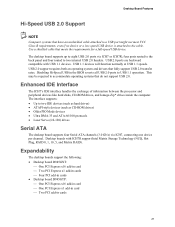
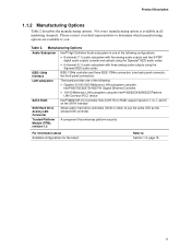
... Up to three IEEE 1394a ports • One port routed to the back panel • Two ports routed to two IEEE 1394a headers • Intel® 82562GZ 10/100 Mbit/sec Platform LAN Connect (PLC) device with RJ-45 connector • Intel® 82573E or 82573V Gigabit Ethernet Controller with RJ-45 connector •...; Microsoft Windows XP Home Edition • Microsoft Windows 2000 11 Table 2. Desktop Board Features Manufacturing Options Table 2 shows the manufacturing options for desktop board D945GNT/D945GTP.
... Up to three IEEE 1394a ports • One port routed to the back panel • Two ports routed to two IEEE 1394a headers • Intel® 82562GZ 10/100 Mbit/sec Platform LAN Connect (PLC) device with RJ-45 connector • Intel® 82573E or 82573V Gigabit Ethernet Controller with RJ-45 connector •...; Microsoft Windows XP Home Edition • Microsoft Windows 2000 11 Table 2. Desktop Board Features Manufacturing Options Table 2 shows the manufacturing options for desktop board D945GNT/D945GTP.
Product Guide
Page 21
... Two PCI Express x1 add-in cards ⎯ Four PCI add-in cards • Desktop board D945GTP: ⎯ One PCI Express x16 add-in card ⎯ One PCI Express x1 add-in card...(3.0 Gb/s) via ICH7 or ICH7R; four ports routed to the back panel and four routed to eight USB 2.0 ports via ICH7, connecting one device per channel. The interface supports: • Up to USB... USB 1.1 devices will function normally at USB 1.1 speeds. USB 2.0 ports are backward compatible with ICH7R support Intel Matrix Storage Technology (NCQ, Hot Plug, RAID 0, 1, 10, 5, and Matrix RAID). Desktop Board Features ...
... Two PCI Express x1 add-in cards ⎯ Four PCI add-in cards • Desktop board D945GTP: ⎯ One PCI Express x16 add-in card ⎯ One PCI Express x1 add-in card...(3.0 Gb/s) via ICH7 or ICH7R; four ports routed to the back panel and four routed to eight USB 2.0 ports via ICH7, connecting one device per channel. The interface supports: • Up to USB... USB 1.1 devices will function normally at USB 1.1 speeds. USB 2.0 ports are backward compatible with ICH7R support Intel Matrix Storage Technology (NCQ, Hot Plug, RAID 0, 1, 10, 5, and Matrix RAID). Desktop Board Features ...

Product Guide
Page 27
...; Install and remove a processor and memory • Install and remove a PCI Express x16 card • Connect the IDE and Serial ATA cables • Connect internal headers • Set up flexible 6-channel audio with jack re-tasking • Connect fans and power cables • Locate other connectors • Set the BIOS configuration jumper •... associated with personal computers and with the safety practices and regulatory compliance required for regulatory requirements. 27 NOTE Refer to operate even though the front panel power button is off.
...; Install and remove a processor and memory • Install and remove a PCI Express x16 card • Connect the IDE and Serial ATA cables • Connect internal headers • Set up flexible 6-channel audio with jack re-tasking • Connect fans and power cables • Locate other connectors • Set the BIOS configuration jumper •... associated with personal computers and with the safety practices and regulatory compliance required for regulatory requirements. 27 NOTE Refer to operate even though the front panel power button is off.

Product Guide
Page 43
... Ground USB A USB B Power (+5V) 1 2 Power (+5V) D- 3 4 D- Ground 3 4 Ground E TPA2+ 5 6 TPA2- +12 V 7 8 +12 V Key (no pin) 10 N/C 9 No Connection On/Off 87 Reset 65 C 43 Power LED HD LED 21 A 12 3 B 1 Item A B C D E F Description Chassis intrusion Alternate power LED Front... panel Hi-speed USB 2.0 (two) IEEE 1394a (two, optional) Front panel audio Figure 21. Port1L 1 2 GND F Port1R Port2R 34 56 Presence# Sense1_Ret Sense_Send 7 Key (no pin) Port2L 9 ...
... Ground USB A USB B Power (+5V) 1 2 Power (+5V) D- 3 4 D- Ground 3 4 Ground E TPA2+ 5 6 TPA2- +12 V 7 8 +12 V Key (no pin) 10 N/C 9 No Connection On/Off 87 Reset 65 C 43 Power LED HD LED 21 A 12 3 B 1 Item A B C D E F Description Chassis intrusion Alternate power LED Front... panel Hi-speed USB 2.0 (two) IEEE 1394a (two, optional) Front panel audio Figure 21. Port1L 1 2 GND F Port1R Port2R 34 56 Presence# Sense1_Ret Sense_Send 7 Key (no pin) Port2L 9 ...
Product Guide
Page 44
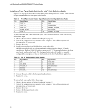
Intel Desktop Board D945GNT/D945GTP Product Guide Installing a Front Panel Audio Solution for the front panel audio header. Turn off the computer and disconnect the AC power cord. 3. Table 9. Front Panel Audio Header Signal Names for Intel High Definition Audio Pin Signal Name 1 PORT 1L 3...SENSE2_RETURN To install the cable that connects the front panel audio solution to be manually configured for microphone or line out functionality in the Intel Audio Studio application. The front panel audio jacks will need to the front panel audio header, follow these steps:...
Intel Desktop Board D945GNT/D945GTP Product Guide Installing a Front Panel Audio Solution for the front panel audio header. Turn off the computer and disconnect the AC power cord. 3. Table 9. Front Panel Audio Header Signal Names for Intel High Definition Audio Pin Signal Name 1 PORT 1L 3...SENSE2_RETURN To install the cable that connects the front panel audio solution to be manually configured for microphone or line out functionality in the Intel Audio Studio application. The front panel audio jacks will need to the front panel audio header, follow these steps:...

Product Guide
Page 46
Intel Desktop Board D945GNT/D945GTP Product Guide Connecting the Front Panel Header Before connecting the front panel header, observe the precautions in "Before You Begin" on page 43 for the front panel header. Table 13. Table 13 shows the pin assignments for the location of the multi-colored front panel header. Front Panel Header Signal Names Pin Signal In/Out...
Intel Desktop Board D945GNT/D945GTP Product Guide Connecting the Front Panel Header Before connecting the front panel header, observe the precautions in "Before You Begin" on page 43 for the front panel header. Table 13. Table 13 shows the pin assignments for the location of the multi-colored front panel header. Front Panel Header Signal Names Pin Signal In/Out...

Product Guide
Page 47
... configurations. After installing the SigmaTel audio driver from the Intel Express Installer driver CD-ROM, the multi-channel audio feature can be enabled. Back Panel Audio Connectors for Flexible 6-Channel Audio System Multi-Channel Analog Audio Connect two speakers to the front left /right out Center/LFE... Mic In Figure 22. For 6-channel audio, connect two additional speakers to the center LFE out (C). 47 A B C Item A B C OM15694 Description Rear left/right out or Line In Front left /right out (B) and two speakers to D945GNT/D945GTP desktop boards with the triple-stack audio connector....
... configurations. After installing the SigmaTel audio driver from the Intel Express Installer driver CD-ROM, the multi-channel audio feature can be enabled. Back Panel Audio Connectors for Flexible 6-Channel Audio System Multi-Channel Analog Audio Connect two speakers to the front left /right out Center/LFE... Mic In Figure 22. For 6-channel audio, connect two additional speakers to the center LFE out (C). 47 A B C Item A B C OM15694 Description Rear left/right out or Line In Front left /right out (B) and two speakers to D945GNT/D945GTP desktop boards with the triple-stack audio connector....

Product Specification
Page 7
Single Channel (Asymmetric) Mode Configuration with Three DIMMs 18 6. Front/Back Panel Audio Connector Options for Front Panel Connector 62 22. Thermal Sensors and Fan Connectors 37 16. Connection Diagram for 8-Channel (7.1) Audio Subsystem .... 29 10. 8-channel (7.1) Audio Subsystem Block ...Memory Channel and DIMM Configuration 17 4. Dual Channel (Interleaved) Mode Configuration with One DIMM 20 8. Back Panel Connectors for IEEE 1394a Connectors 64 24. Connection Diagram for 8-Channel (7.1) Audio Subsystem 54 19. I /O Shield Dimensions for Boards with the 6-Channel ...
Single Channel (Asymmetric) Mode Configuration with Three DIMMs 18 6. Front/Back Panel Audio Connector Options for Front Panel Connector 62 22. Thermal Sensors and Fan Connectors 37 16. Connection Diagram for 8-Channel (7.1) Audio Subsystem .... 29 10. 8-channel (7.1) Audio Subsystem Block ...Memory Channel and DIMM Configuration 17 4. Dual Channel (Interleaved) Mode Configuration with One DIMM 20 8. Back Panel Connectors for IEEE 1394a Connectors 64 24. Connection Diagram for 8-Channel (7.1) Audio Subsystem 54 19. I /O Shield Dimensions for Boards with the 6-Channel ...
Product Specification
Page 11
..., two front-panel connectors) LAN subsystem SATA RAID The board provides one of the following: • Gigabit (10/100/1000 Mbits/sec) LAN subsystem using the Intel® 82573E/82573V/82574V Gigabit Ethernet Controller • 10/100 Mbits/sec LAN subsystem using the Intel® 82562GX/82562GZ Platform LAN Connect (PLC) device Intel® 82801GR...
..., two front-panel connectors) LAN subsystem SATA RAID The board provides one of the following: • Gigabit (10/100/1000 Mbits/sec) LAN subsystem using the Intel® 82573E/82573V/82574V Gigabit Ethernet Controller • 10/100 Mbits/sec LAN subsystem using the Intel® 82562GX/82562GZ Platform LAN Connect (PLC) device Intel® 82801GR...

Product Specification
Page 14
...Panel/Front Panel USB Ports Parallel ATA IDE Connector Parallel ATA IDE Interface LGA775 Processor Socket System Bus (1066/800/533 MHz) PCI Express x16 Interface PCI Express x16 Connector Intel 945G Chipset Intel...PS/2 Keyboard Diskette Drive Connector Intel 82801G I/O Controller Hub (ICH7) Serial Peripheral Interface (SPI) Flash Device DMI Interconnect High Definition Audio Link LAN Connect Interface VGA Port Channel A... Jack (optional) S/PDIF (optional) Figure 2. Intel Desktop Board D945GTP Technical Product Specification 1.1.4 Block Diagram Figure 2 is a block diagram of the...
...Panel/Front Panel USB Ports Parallel ATA IDE Connector Parallel ATA IDE Interface LGA775 Processor Socket System Bus (1066/800/533 MHz) PCI Express x16 Interface PCI Express x16 Connector Intel 945G Chipset Intel...PS/2 Keyboard Diskette Drive Connector Intel 82801G I/O Controller Hub (ICH7) Serial Peripheral Interface (SPI) Flash Device DMI Interconnect High Definition Audio Link LAN Connect Interface VGA Port Channel A... Jack (optional) S/PDIF (optional) Figure 2. Intel Desktop Board D945GTP Technical Product Specification 1.1.4 Block Diagram Figure 2 is a block diagram of the...
Product Specification
Page 22
... additional system memory to the graphics buffer as set in the BIOS Setup program) for TV-out / TV-in and DVI digital display connections ⎯ Supports flat panels up to 2048 x 1536 at 60Hz or digital CRT/HDTV at 1920 x 1080 at 75 Hz refresh (QXGA) ⎯ DDC2B compliant... graphics functions. Up to 128 MB can be allocated to DVMT on systems that have 512 MB or more of total installed system memory. Intel Desktop Board D945GTP Technical Product Specification • Video ⎯ Hardware motion compensation for MPEG2 ⎯ Software DVD at 30 fps full screen • Display ...
... additional system memory to the graphics buffer as set in the BIOS Setup program) for TV-out / TV-in and DVI digital display connections ⎯ Supports flat panels up to 2048 x 1536 at 60Hz or digital CRT/HDTV at 1920 x 1080 at 75 Hz refresh (QXGA) ⎯ DDC2B compliant... graphics functions. Up to 128 MB can be allocated to DVMT on systems that have 512 MB or more of total installed system memory. Intel Desktop Board D945GTP Technical Product Specification • Video ⎯ Hardware motion compensation for MPEG2 ⎯ Software DVD at 30 fps full screen • Display ...

Product Specification
Page 27
...BIOS Setup program to set the parallel port mode. NOTE The keyboard is supported in the bottom PS/2 connector and the mouse is connected or disconnected. For information about The location of the serial port A connector Refer to the computer should be turned off before a keyboard...BIOS Setup program provides configuration options for the legacy I/O controller. 1.8.1 Serial Port The Serial port A connector is located on the back panel. For information about The location of the keyboard and mouse connectors Refer to 115.2 kbits/sec with serialized IRQ support for PCI Conventional ...
...BIOS Setup program to set the parallel port mode. NOTE The keyboard is supported in the bottom PS/2 connector and the mouse is connected or disconnected. For information about The location of the serial port A connector Refer to the computer should be turned off before a keyboard...BIOS Setup program provides configuration options for the legacy I/O controller. 1.8.1 Serial Port The Serial port A connector is located on the back panel. For information about The location of the keyboard and mouse connectors Refer to 115.2 kbits/sec with serialized IRQ support for PCI Conventional ...
Product Specification
Page 28
Intel Desktop Board D945GTP Technical Product Specification 1.9 Audio Subsystem The board supports the Intel High Definition audio subsystem based on which subsystem is connected to -noise (S/N) ratio of the back panel audio connectors are available from Intel's World Wide Web site. The back panel audio jacks are capable of retasking according to user's definition, or can be automatically...
Intel Desktop Board D945GTP Technical Product Specification 1.9 Audio Subsystem The board supports the Intel High Definition audio subsystem based on which subsystem is connected to -noise (S/N) ratio of the back panel audio connectors are available from Intel's World Wide Web site. The back panel audio jacks are capable of retasking according to user's definition, or can be automatically...

Product Specification
Page 53
... use these groups: • Back panel I/O connectors (see page 55) • Component-side I/O connectors (see page 53) 2.8.1 Back Panel Connectors The back panel configuration is dependent upon which audio subsystem is present. The configurations are not overcurrent protected and should connect only to devices inside the computer's ...This section describes the board's connectors. Technical Reference 2.8 Connectors CAUTION Only the following connectors have overcurrent protection: back panel USB, front panel USB, and PS/2. The other internal connectors are as fans and internal peripherals.
... use these groups: • Back panel I/O connectors (see page 55) • Component-side I/O connectors (see page 53) 2.8.1 Back Panel Connectors The back panel configuration is dependent upon which audio subsystem is present. The configurations are not overcurrent protected and should connect only to devices inside the computer's ...This section describes the board's connectors. Technical Reference 2.8 Connectors CAUTION Only the following connectors have overcurrent protection: back panel USB, front panel USB, and PS/2. The other internal connectors are as fans and internal peripherals.

Product Specification
Page 54
...Jack [Blue] M Digital audio out optical N Mic in Figure 18. NOTE The back panel audio line out connector is designed to this output. Table 16. Intel Desktop Board D945GTP Technical Product Specification 2.8.1.1 Back Panel Connectors For 8-Channel (7.1) Audio Subsystem Figure 18 shows the location of the back...the back panel connectors identified in /Retasking Jack [Pink] O Front left/right channel audio out/Two channel audio line out/Retasking Jack [Lime green] 54 The figure legend (Table 16) lists the colors used (when applicable). The back panel connectors are connected to ...
...Jack [Blue] M Digital audio out optical N Mic in Figure 18. NOTE The back panel audio line out connector is designed to this output. Table 16. Intel Desktop Board D945GTP Technical Product Specification 2.8.1.1 Back Panel Connectors For 8-Channel (7.1) Audio Subsystem Figure 18 shows the location of the back...the back panel connectors identified in /Retasking Jack [Pink] O Front left/right channel audio out/Two channel audio line out/Retasking Jack [Lime green] 54 The figure legend (Table 16) lists the colors used (when applicable). The back panel connectors are connected to ...

Product Specification
Page 55
...] J Mic in/Retasking Jack [Pink] K Front left/right channel audio out/Two channel audio line out/Retasking Jack [Lime green] 55 Table 17. The back panel connectors are connected to power headphones or amplified speakers only. Technical Reference 2.8.1.2 Back Panel Connectors For 6-Channel (5.1) Audio Subsystem Figure 19 shows the location of the back...
...] J Mic in/Retasking Jack [Pink] K Front left/right channel audio out/Two channel audio line out/Retasking Jack [Lime green] 55 Table 17. The back panel connectors are connected to power headphones or amplified speakers only. Technical Reference 2.8.1.2 Back Panel Connectors For 6-Channel (5.1) Audio Subsystem Figure 19 shows the location of the back...

Product Specification
Page 58
... # INTEGRATOR'S NOTE The front panel audio connector is colored yellow. Table 20. SCSI Hard Drive Activity LED Connector (Optional) Pin Signal Name 1 SCSI_ACT# 2 No connect Signal Name Ground Presence# (dongle... present) Port E [Port 1] Sense return (jack detection) Key Port F [Port 2] Sense return (jack detection) Table 22. Serial ATA Connectors Pin Signal Name 1 Ground 2 TXP 3 TXN 4 Ground 5 RXN 6 RXP 7 Ground 58 Chassis Intrusion Connector Pin Signal Name 1 Intruder 2 Ground Table 21. Intel Desktop Board D945GTP...
... # INTEGRATOR'S NOTE The front panel audio connector is colored yellow. Table 20. SCSI Hard Drive Activity LED Connector (Optional) Pin Signal Name 1 SCSI_ACT# 2 No connect Signal Name Ground Presence# (dongle... present) Port E [Port 1] Sense return (jack detection) Key Port F [Port 2] Sense return (jack detection) Table 22. Serial ATA Connectors Pin Signal Name 1 Ground 2 TXP 3 TXN 4 Ground 5 RXN 6 RXP 7 Ground 58 Chassis Intrusion Connector Pin Signal Name 1 Intruder 2 Ground Table 21. Intel Desktop Board D945GTP...

Product Specification
Page 61
.../Sleep LED Connector Pin Signal Name 1 HDR_BLNK_GRN 2 Not connected 3 HDR_BLNK_YEL In/Out Out Out Description Front panel green LED Front panel yellow LED 61 The SMBus is routed to support only a PCI Express x1 link when the Intel GMA950 graphics controller is enabled. 2.8.2.3 Auxiliary Front Panel Power/Sleep LED Connector Pins 1 and 3 of this connector...
.../Sleep LED Connector Pin Signal Name 1 HDR_BLNK_GRN 2 Not connected 3 HDR_BLNK_YEL In/Out Out Out Description Front panel green LED Front panel yellow LED 61 The SMBus is routed to support only a PCI Express x1 link when the Intel GMA950 graphics controller is enabled. 2.8.2.3 Auxiliary Front Panel Power/Sleep LED Connector Pins 1 and 3 of this connector...


