Product Guide
Page 2
.../TV technician for use . Revision History Revision -001 -002 -003 -004 Revision History First release of the Intel® Desktop Board D945GCZ Product Guide Second release of the Intel® Desktop Board D945GCZ Product Guide Third release of the Intel® Desktop Board D945GCZ Product Guide Added operating system support Date March 2005 August 2005 April 2006 February 2007 If an FCC...
.../TV technician for use . Revision History Revision -001 -002 -003 -004 Revision History First release of the Intel® Desktop Board D945GCZ Product Guide Second release of the Intel® Desktop Board D945GCZ Product Guide Third release of the Intel® Desktop Board D945GCZ Product Guide Added operating system support Date March 2005 August 2005 April 2006 February 2007 If an FCC...
Product Guide
Page 3
may not be supported without further evaluation by Intel. Intended Audience The Product Guide is not intended for Intel® Desktop Board D945GCZ. NOTE Notes call attention to update the BIOS 4 Configuring for RAID (Intel® Matrix Storage Technology) Requires Microsoft Windows* XP or 2000 and SATA Hard Drive(s): information about configuring the system for installation in...
may not be supported without further evaluation by Intel. Intended Audience The Product Guide is not intended for Intel® Desktop Board D945GCZ. NOTE Notes call attention to update the BIOS 4 Configuring for RAID (Intel® Matrix Storage Technology) Requires Microsoft Windows* XP or 2000 and SATA Hard Drive(s): information about configuring the system for installation in...
Product Guide
Page 4
...(1024 bytes) MB Megabyte (1,048,576 bytes) Mbit Megabit (1,048,576 bits) MHz Megahertz (one million hertz) Box Contents • Intel Desktop Board D945GCZ • I/O shield • One ATA-66/100 cable • Two locking Serial ATA cables • One diskette drive cable &#...caution statement label • Intel® Express Installer driver CD-ROM • Intel Express Installer software CD-ROM or DVD-ROM • Trusted Platform Module Quick Reference manual (optional) • Trusted Platform Warning Label (optional) iv Intel Desktop Board D945GCZ Product Guide Terminology The ...
...(1024 bytes) MB Megabyte (1,048,576 bytes) Mbit Megabit (1,048,576 bits) MHz Megahertz (one million hertz) Box Contents • Intel Desktop Board D945GCZ • I/O shield • One ATA-66/100 cable • Two locking Serial ATA cables • One diskette drive cable &#...caution statement label • Intel® Express Installer driver CD-ROM • Intel Express Installer software CD-ROM or DVD-ROM • Trusted Platform Module Quick Reference manual (optional) • Trusted Platform Warning Label (optional) iv Intel Desktop Board D945GCZ Product Guide Terminology The ...
Product Guide
Page 6
Intel Desktop Board D945GCZ Product Guide Installing and Removing the Desktop Board 29 Installing and Removing a Processor 30 Installing a Processor 30 Installing the Processor Fan Heat Sink 33 Connecting the Processor Fan Heat Sink Cable 33 Removing ... Express x16 Card 38 Connecting the IDE Cable 39 Connecting a Serial ATA (SATA) Cable 40 Connecting Internal Headers 41 Installing a Front Panel Audio Solution for Intel® High Definition Audio 42 Connecting USB 2.0 Headers 43 Connecting IEEE 1394a Headers (Optional 43 Connecting the Front Panel Header 43 Setting Up the Flexible...
Intel Desktop Board D945GCZ Product Guide Installing and Removing the Desktop Board 29 Installing and Removing a Processor 30 Installing a Processor 30 Installing the Processor Fan Heat Sink 33 Connecting the Processor Fan Heat Sink Cable 33 Removing ... Express x16 Card 38 Connecting the IDE Cable 39 Connecting a Serial ATA (SATA) Cable 40 Connecting Internal Headers 41 Installing a Front Panel Audio Solution for Intel® High Definition Audio 42 Connecting USB 2.0 Headers 43 Connecting IEEE 1394a Headers (Optional 43 Connecting the Front Panel Header 43 Setting Up the Flexible...

Product Guide
Page 7
...Heat Sink Cable to the Processor Fan Connector ........33 13. Dual Configuration Example 3 35 16. Removing the Battery 54 27. Desktop Board D945GCZ Mounting Screw Hole Locations 29 6. Dual Configuration Example 1 34 14. Location of Fan Headers 45 23. Back Panel Audio Connectors...Touch the Socket Contacts 30 8. Internal Headers ...41 21. Location of Standby Power Indicator 22 4. Location of Other Connectors on Desktop Board D945GCZ 47 25. Dual Configuration Example 2 34 15. Remove the Protective Socket Cover 31 9. Inserting a PCI Express x16 Card and...
...Heat Sink Cable to the Processor Fan Connector ........33 13. Dual Configuration Example 3 35 16. Removing the Battery 54 27. Desktop Board D945GCZ Mounting Screw Hole Locations 29 6. Dual Configuration Example 1 34 14. Location of Fan Headers 45 23. Back Panel Audio Connectors...Touch the Socket Contacts 30 8. Internal Headers ...41 21. Location of Standby Power Indicator 22 4. Location of Other Connectors on Desktop Board D945GCZ 47 25. Dual Configuration Example 2 34 15. Remove the Protective Socket Cover 31 9. Inserting a PCI Express x16 Card and...
Product Guide
Page 8
...for the BIOS Setup Program Modes 48 14. IEEE 1394a Header Signal Names 43 12. Beep Codes...61 15. Desktop Board D945GCZ Memory Configurations 15 6. Jumper Settings for Intel High Definition Audio 42 9. BIOS Error Messages 61 16. Manufacturing Options 10 3. RJ-45 10/100 Ethernet ... 42 10. Product Certification Markings 70 viii RJ-45 10/100/1000 Gigabit Ethernet LAN Connector LEDs 18 8. Desktop Board D945GCZ Components 13 4. Safety Regulations...63 17. Intel Desktop Board D945GCZ Product Guide Tables 1. Front Panel Header Signal Names 43 13. Lead-Free...
...for the BIOS Setup Program Modes 48 14. IEEE 1394a Header Signal Names 43 12. Beep Codes...61 15. Desktop Board D945GCZ Memory Configurations 15 6. Jumper Settings for Intel High Definition Audio 42 9. BIOS Error Messages 61 16. Manufacturing Options 10 3. RJ-45 10/100 Ethernet ... 42 10. Product Certification Markings 70 viii RJ-45 10/100/1000 Gigabit Ethernet LAN Connector LEDs 18 8. Desktop Board D945GCZ Components 13 4. Safety Regulations...63 17. Intel Desktop Board D945GCZ Product Guide Tables 1. Front Panel Header Signal Names 43 13. Lead-Free...
Product Guide
Page 9
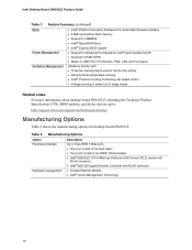
...; PS/2* keyboard and mouse ports continued 9 For the latest list of tested memory, refer to the Intel World Wide Web site at: http://support.intel.com/support/motherboards/desktop/ Intel® 945G Express Chipset consisting of: • Intel® 82945G Graphics and Memory Controller Hub (GMCH) with Direct Media Interface •...; High Definition Audio interface • SigmaTel* codec • Two PCI bus add-in less than 4 GB of Intel® Desktop Board D945GCZ. Table 1. This may result in card connectors (SMBus routed to PCI bus 2) • One PCI Express* x16 connector • One ...
...; PS/2* keyboard and mouse ports continued 9 For the latest list of tested memory, refer to the Intel World Wide Web site at: http://support.intel.com/support/motherboards/desktop/ Intel® 945G Express Chipset consisting of: • Intel® 82945G Graphics and Memory Controller Hub (GMCH) with Direct Media Interface •...; High Definition Audio interface • SigmaTel* codec • Two PCI bus add-in less than 4 GB of Intel® Desktop Board D945GCZ. Table 1. This may result in card connectors (SMBus routed to PCI bus 2) • One PCI Express* x16 connector • One ...
Product Guide
Page 10
... Framework for extensible firmware interface • 4 Mbit symmetrical flash memory • Support for SMBIOS • Intel® Rapid BIOS Boot • Intel® Express BIOS Update Power Management • Support for Advanced Configuration and Power Interface (ACPI) • Suspend to : http://support.intel.com/support/motherboards/desktop/ Manufacturing Options Table 2 shows the manufacturing options for desktop board D945GCZ.
... Framework for extensible firmware interface • 4 Mbit symmetrical flash memory • Support for SMBIOS • Intel® Rapid BIOS Boot • Intel® Express BIOS Update Power Management • Support for Advanced Configuration and Power Interface (ACPI) • Suspend to : http://support.intel.com/support/motherboards/desktop/ Manufacturing Options Table 2 shows the manufacturing options for desktop board D945GCZ.
Product Guide
Page 12
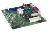
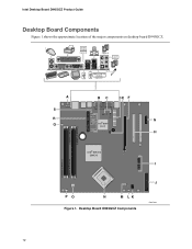
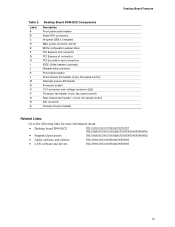
Intel Desktop Board D945GCZ Product Guide Desktop Board Components Figure 1 shows the approximate location of the major components on desktop board D945GCZ. IEEE 1394a (Optional) (Optional) Line In Optical Line Out (Toslink) (Optional) A S R Q BC DE F G R Intel 82801 (ICH7) H Channel A DIMM 0 Channel A DIMM 1 Channel B DIMM 0 Channel B DIMM 1 IntelR 82945G (GMCH) I PO N M LK Figure 1. Desktop Board D945GCZ Components J OM17634 12
Intel Desktop Board D945GCZ Product Guide Desktop Board Components Figure 1 shows the approximate location of the major components on desktop board D945GCZ. IEEE 1394a (Optional) (Optional) Line In Optical Line Out (Toslink) (Optional) A S R Q BC DE F G R Intel 82801 (ICH7) H Channel A DIMM 0 Channel A DIMM 1 Channel B DIMM 0 Channel B DIMM 1 IntelR 82945G (GMCH) I PO N M LK Figure 1. Desktop Board D945GCZ Components J OM17634 12
Product Guide
Page 13
... A B C D E F G H I J K L M N O P Q R S Desktop Board D945GCZ Components Description Front panel audio header Serial ATA connectors Hi-speed USB 2.0 headers Main power connector (2x12) ...more information about: • Desktop board D945GCZ • Supported processors • Audio software and utilities • LAN software and drivers http://www.intel.com/design/motherbd http://support.intel.com/support/motherboards/desktop http://support.intel.com/support/motherboards/desktop http://www.intel.com/design/motherbd http://www.intel.com/design/motherbd 13 Desktop Board Features Table 3.
... A B C D E F G H I J K L M N O P Q R S Desktop Board D945GCZ Components Description Front panel audio header Serial ATA connectors Hi-speed USB 2.0 headers Main power connector (2x12) ...more information about: • Desktop board D945GCZ • Supported processors • Audio software and utilities • LAN software and drivers http://www.intel.com/design/motherbd http://support.intel.com/support/motherboards/desktop http://support.intel.com/support/motherboards/desktop http://www.intel.com/design/motherbd http://www.intel.com/design/motherbd 13 Desktop Board Features Table 3.
Product Guide
Page 14
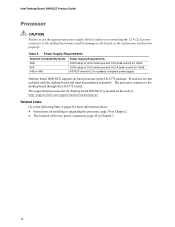
...power supply Desktop board D945GCZ supports an Intel processor in the LGA775 package. Processors are not included with the desktop board and must be purchased separately. The supported processors list for desktop board D945GCZ is located on the web at: http://support.intel.com/support/motherboards/desktop/ Related Links...of the two power connectors, page 45 in Chapter 2 14 The processor connects to the board, or the system may not function properly. Intel Desktop Board D945GCZ Product Guide Processor CAUTION Failure to use the appropriate power supply (below) and/or not ...
...power supply Desktop board D945GCZ supports an Intel processor in the LGA775 package. Processors are not included with the desktop board and must be purchased separately. The supported processors list for desktop board D945GCZ is located on the web at: http://support.intel.com/support/motherboards/desktop/ Related Links...of the two power connectors, page 45 in Chapter 2 14 The processor connects to the board, or the system may not function properly. Intel Desktop Board D945GCZ Product Guide Processor CAUTION Failure to use the appropriate power supply (below) and/or not ...
Product Guide
Page 15
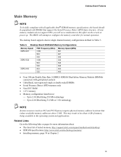
...This may result in less than 4 GB of tested memory, http://support.intel.com/support/motherboards/desktop/ • SDRAM specifications, http://www.intel.com/technology/memory/ • Installing memory, page 34 in Table 5. The desktop board supports dual or single channel memory configurations defined in Chapter 2 15 If... Presence Detect (SPD) data structure. The BIOS will see a notification to this effect on the screen at power up. Desktop Board D945GCZ Memory Configurations Memory Speed FSB Frequency (MHz) Memory Speed (MHz) DDR2-667 1066 667 800 667 533 533 DDR2-533 ...
...This may result in less than 4 GB of tested memory, http://support.intel.com/support/motherboards/desktop/ • SDRAM specifications, http://www.intel.com/technology/memory/ • Installing memory, page 34 in Table 5. The desktop board supports dual or single channel memory configurations defined in Chapter 2 15 If... Presence Detect (SPD) data structure. The BIOS will see a notification to this effect on the screen at power up. Desktop Board D945GCZ Memory Configurations Memory Speed FSB Frequency (MHz) Memory Speed (MHz) DDR2-667 1066 667 800 667 533 533 DDR2-533 ...
Product Guide
Page 16
...; Microphone in ⎯ Center/LFE out (optional) ⎯ Rear left and right out (optional) 16 Intel Desktop Board D945GCZ Product Guide Intel® 945G Express Chipset The Intel 945G Express Chipset consists of the audio devices: ⎯ Line in ⎯ Line out ⎯ Microphone in...tasking • S/N (signal-to the following link for more information about the Intel 945G Express Chipset: http://developer.intel.com/design/nav/pcserver.htm Graphics Subsystem Desktop board D945GCZ includes the following connectors: • Front panel audio connector, including functionality for ...
...; Microphone in ⎯ Center/LFE out (optional) ⎯ Rear left and right out (optional) 16 Intel Desktop Board D945GCZ Product Guide Intel® 945G Express Chipset The Intel 945G Express Chipset consists of the audio devices: ⎯ Line in ⎯ Line out ⎯ Microphone in...tasking • S/N (signal-to the following link for more information about the Intel 945G Express Chipset: http://developer.intel.com/design/nav/pcserver.htm Graphics Subsystem Desktop board D945GCZ includes the following connectors: • Front panel audio connector, including functionality for ...

Product Guide
Page 18
... Off 10 Mbits/sec data rate is selected On (steady state) 100 Mbits/sec data rate is selected Table 7 describes the LED states when the board is powered up and the 10/100 Ethernet LAN subsystem is operating. OM17386 Figure 2. LAN Port LED Locations Table 6 describes the LED states when the... up and the 10/100/1000 Gigabit Ethernet LAN subsystem is occurring 10 Mb/s data rate 100 Mb/s data rate 1000 Mb/s data rate 18 Intel Desktop Board D945GCZ Product Guide RJ-45 LAN Connector LEDs Two LEDs are built into the RJ-45 LAN port located on the back panel (see Figure 2).
... Off 10 Mbits/sec data rate is selected On (steady state) 100 Mbits/sec data rate is selected Table 7 describes the LED states when the board is powered up and the 10/100 Ethernet LAN subsystem is operating. OM17386 Figure 2. LAN Port LED Locations Table 6 describes the LED states when the... up and the 10/100/1000 Gigabit Ethernet LAN subsystem is occurring 10 Mb/s data rate 100 Mb/s data rate 1000 Mb/s data rate 18 Intel Desktop Board D945GCZ Product Guide RJ-45 LAN Connector LEDs Two LEDs are built into the RJ-45 LAN port located on the back panel (see Figure 2).
Product Guide
Page 20
... options are then available for viewing and changing depending on the desktop board. Serial ATA and IDE Auto Configuration If you can boot the... You do not need to access Setup. If only the supervisor password is booted. Chassis Intrusion The board supports a chassis security feature that can be accessed and who can be set , the computer boots without... The password prompt is displayed before the computer is set for the BIOS Setup and for a password. Intel Desktop Board D945GCZ Product Guide BIOS The BIOS provides the Power-On Self-Test (POST), the BIOS Setup program, the ...
... options are then available for viewing and changing depending on the desktop board. Serial ATA and IDE Auto Configuration If you can boot the... You do not need to access Setup. If only the supervisor password is booted. Chassis Intrusion The board supports a chassis security feature that can be accessed and who can be set , the computer boots without... The password prompt is displayed before the computer is set for the BIOS Setup and for a password. Intel Desktop Board D945GCZ Product Guide BIOS The BIOS provides the Power-On Self-Test (POST), the BIOS Setup program, the ...
Product Guide
Page 22
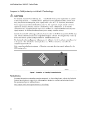
...desktop board must be capable of Standby Power Indicator OM17635 Related Links: For more information on the front panel, the sleep state is standby power to the system. If the standby current necessary to support multiple wake events from the left-hand menu: http://support.intel.com/support/motherboards/desktop... Instantly Available (ACPI S3 sleep state) configuration. The desktop board's standby power indicator, shown in Figure 3, is lit when there is indicated by the LED turning amber. Intel Desktop Board D945GCZ Product Guide Suspend to RAM (Instantly Available PC Technology)...
...desktop board must be capable of Standby Power Indicator OM17635 Related Links: For more information on the front panel, the sleep state is standby power to the system. If the standby current necessary to support multiple wake events from the left-hand menu: http://support.intel.com/support/motherboards/desktop... Instantly Available (ACPI S3 sleep state) configuration. The desktop board's standby power indicator, shown in Figure 3, is lit when there is indicated by the LED turning amber. Intel Desktop Board D945GCZ Product Guide Suspend to RAM (Instantly Available PC Technology)...

Product Guide
Page 26
... all of these instructions and the instructions supplied with regional laws and regulations. If you do not follow the steps in each procedure in this board. Intel Desktop Board D945GCZ Product Guide Follow these guidelines before you begin: • Always follow these instructions and the instructions provided by wearing an antistatic wrist strap and attaching...
... all of these instructions and the instructions supplied with regional laws and regulations. If you do not follow the steps in each procedure in this board. Intel Desktop Board D945GCZ Product Guide Follow these guidelines before you begin: • Always follow these instructions and the instructions provided by wearing an antistatic wrist strap and attaching...

Product Guide
Page 28
..., protects internal components from the chassis supplier. Press the shield into place so that it fits tightly and securely. Installing the I /O shield before installing the desktop board in the chassis. When installed in Figure 4. OR OR OM17614 Figure 4. Install the I /O Shield 28 Intel Desktop Board D945GCZ Product Guide Installing the I/O Shield The desktop board comes with an I/O shield.
..., protects internal components from the chassis supplier. Press the shield into place so that it fits tightly and securely. Installing the I /O shield before installing the desktop board in the chassis. When installed in Figure 4. OR OR OM17614 Figure 4. Install the I /O Shield 28 Intel Desktop Board D945GCZ Product Guide Installing the I/O Shield The desktop board comes with an I/O shield.
Product Guide
Page 29
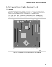
... equipment damage. Installing and Replacing Desktop Board Components Installing and Removing the Desktop Board CAUTION Only qualified technical personnel should do this procedure. Figure 5 shows the location of the seven mounting screw holes for instructions on installing and removing the desktop board. OM17636 Figure 5. Failure to your chassis manual for desktop board D945GCZ. Desktop Board D945GCZ Mounting Screw Hole Locations 29 Refer...
... equipment damage. Installing and Replacing Desktop Board Components Installing and Removing the Desktop Board CAUTION Only qualified technical personnel should do this procedure. Figure 5 shows the location of the seven mounting screw holes for instructions on installing and removing the desktop board. OM17636 Figure 5. Failure to your chassis manual for desktop board D945GCZ. Desktop Board D945GCZ Mounting Screw Hole Locations 29 Refer...

Product Guide
Page 30
... touch the socket contacts (see Figure 6, A and B). Observe the precautions in "Before You Begin" on page 22). Lift Socket Lever 3. Intel Desktop Board D945GCZ Product Guide Installing and Removing a Processor Instructions on how to install the processor to do so could damage the processor and the... board. A B OM17210 Figure 6. Installing a Processor CAUTION Before installing or removing the processor, make sure the AC power has been removed by pushing the lever down and away from the computer; Failure to the desktop board are given below.
... touch the socket contacts (see Figure 6, A and B). Observe the precautions in "Before You Begin" on page 22). Lift Socket Lever 3. Intel Desktop Board D945GCZ Product Guide Installing and Removing a Processor Instructions on how to install the processor to do so could damage the processor and the... board. A B OM17210 Figure 6. Installing a Processor CAUTION Before installing or removing the processor, make sure the AC power has been removed by pushing the lever down and away from the computer; Failure to the desktop board are given below.


