Product Guide
Page 3
..., such as follows: 1 Desktop Board Features: a summary of product features 2 Installing and Replacing Desktop Board Components: instructions on how to install the Desktop Board and other hardware components 3 Updating the BIOS: a description of data. NOTE Notes call attention to update the BIOS A BIOS Error Messages: information about board layout, component installation, and regulatory requirements for Intel® Desktop Board D945GCLF2D. Intended Audience The Product...
..., such as follows: 1 Desktop Board Features: a summary of product features 2 Installing and Replacing Desktop Board Components: instructions on how to install the Desktop Board and other hardware components 3 Updating the BIOS: a description of data. NOTE Notes call attention to update the BIOS A BIOS Error Messages: information about board layout, component installation, and regulatory requirements for Intel® Desktop Board D945GCLF2D. Intended Audience The Product...
Product Guide
Page 5
...Desktop Board Features Desktop Board Components 10 Processor ...12 Main Memory...12 Intel® 945GC Express Chipset 13 Onboard Audio Subsystem 13 Input/Output (I/O) Controller 14 LAN Subsystem 15 LAN Subsystem Software 15 LAN Status LEDs 15 Hi-Speed USB 2.0 Support 16 Enhanced IDE Interface 16 Serial ATA...16 Expandability...16 BIOS...Supply Overload 22 Observe Safety and Regulatory Requirements 22 Installing the I/O Shield 23 Installing and Removing the Desktop Board 24 Installing and Removing Memory 25 Installing DIMMs 25 Removing DIMMs 27 Connecting the IDE Cable 27 ...
...Desktop Board Features Desktop Board Components 10 Processor ...12 Main Memory...12 Intel® 945GC Express Chipset 13 Onboard Audio Subsystem 13 Input/Output (I/O) Controller 14 LAN Subsystem 15 LAN Subsystem Software 15 LAN Status LEDs 15 Hi-Speed USB 2.0 Support 16 Enhanced IDE Interface 16 Serial ATA...16 Expandability...16 BIOS...Supply Overload 22 Observe Safety and Regulatory Requirements 22 Installing the I/O Shield 23 Installing and Removing the Desktop Board 24 Installing and Removing Memory 25 Installing DIMMs 25 Removing DIMMs 27 Connecting the IDE Cable 27 ...
Product Guide
Page 6
Intel Desktop Board D945GCLF2D Product Guide Connecting a Chassis Fan 33 Connecting Power Supply Cables 34 Setting the BIOS Configuration Jumper 35 Clearing Passwords 36 Replacing the Battery 37 3 Updating the BIOS Updating the BIOS with the Intel® Express BIOS Update Utility 43 Updating the BIOS with the Iflash Memory Update Utility 43 Obtaining the BIOS Update File 43 Updating the BIOS with...
Intel Desktop Board D945GCLF2D Product Guide Connecting a Chassis Fan 33 Connecting Power Supply Cables 34 Setting the BIOS Configuration Jumper 35 Clearing Passwords 36 Replacing the Battery 37 3 Updating the BIOS Updating the BIOS with the Intel® Express BIOS Update Utility 43 Updating the BIOS with the Iflash Memory Update Utility 43 Obtaining the BIOS Update File 43 Updating the BIOS with...
Product Guide
Page 7
... Header Signal Names 32 7. Lead-Free Second Level Interconnect Marks 52 14. Intel Desktop Board D945GCLF2D Components 10 2. Installing the I/O Shield 23 6. LAN Status LEDs 15 4. Safety Standards 47 13. Internal Headers 30 12. Front Panel Audio Header Signal Names for the BIOS Setup Program Modes 36 9. S/PDIF Connector Signal Names 31 6. Hi-Speed USB...
... Header Signal Names 32 7. Lead-Free Second Level Interconnect Marks 52 14. Intel Desktop Board D945GCLF2D Components 10 2. Installing the I/O Shield 23 6. LAN Status LEDs 15 4. Safety Standards 47 13. Internal Headers 30 12. Front Panel Audio Header Signal Names for the BIOS Setup Program Modes 36 9. S/PDIF Connector Signal Names 31 6. Hi-Speed USB...
Product Guide
Page 9
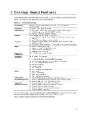
... Intel® Atom™ processor • One 240-pin SDRAM Dual Inline Memory Module (DIMM) socket • 533 MHz single channel DDR2 SDRAM interface • Supports up to 2 GB of system memory Intel® 945GC Express Chipset consisting of Intel® Desktop Board D945GCLF2D. 1 Desktop Board ... x64 Edition • Microsoft Windows XP Home For more information about Intel Desktop Board D945GCLF2D, including the Technical Product Specification (TPS), BIOS updates, and device drivers, go to http://support.intel.com/support/motherboards/desktop/. 9 Table 1 summarizes the features of the...
... Intel® Atom™ processor • One 240-pin SDRAM Dual Inline Memory Module (DIMM) socket • 533 MHz single channel DDR2 SDRAM interface • Supports up to 2 GB of system memory Intel® 945GC Express Chipset consisting of Intel® Desktop Board D945GCLF2D. 1 Desktop Board ... x64 Edition • Microsoft Windows XP Home For more information about Intel Desktop Board D945GCLF2D, including the Technical Product Specification (TPS), BIOS updates, and device drivers, go to http://support.intel.com/support/motherboards/desktop/. 9 Table 1 summarizes the features of the...
Product Guide
Page 12
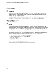
...not support SPD, you will attempt to this effect on the screen at power up. The BIOS will see a notification to configure the memory controller for normal operation. The processor is not customer upgradeable. It supports: • 533 MHz unbuffered, non-registered DDR2 DIMMs ...• Up to 2 GB of memory For the latest list of tested memory, go to the Desktop Board and is soldered to http://support.intel.com/support/motherboards/desktop/. 12 Intel Desktop Board D945GCLF2D Product Guide Processor CAUTION Failure to use an appropriate power supply and/or not connecting the 12 V (2 x 2) ...
...not support SPD, you will attempt to this effect on the screen at power up. The BIOS will see a notification to configure the memory controller for normal operation. The processor is not customer upgradeable. It supports: • 533 MHz unbuffered, non-registered DDR2 DIMMs ...• Up to 2 GB of memory For the latest list of tested memory, go to the Desktop Board and is soldered to http://support.intel.com/support/motherboards/desktop/. 12 Intel Desktop Board D945GCLF2D Product Guide Processor CAUTION Failure to use an appropriate power supply and/or not connecting the 12 V (2 x 2) ...
Product Guide
Page 16
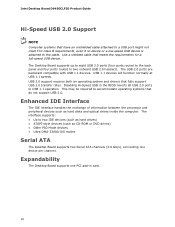
...of information between the processor and peripheral devices such as CD-ROM or DVD drives) • Older PIO Mode devices • Ultra DMA-33/66/100 modes Serial ATA The Desktop Board supports two Serial ATA channels (3.0 Gb/s), connecting one PCI add-in the BIOS reverts all USB ...2.0 ports to accommodate operating systems that fully support USB 2.0 transfer rates. Disabling Hi-Speed USB in card. 16 The Desktop Board supports up to eight USB 2.0 ports (four ports routed to the back panel and four ports routed to the cable. Intel Desktop Board D945GCLF2D ...
...of information between the processor and peripheral devices such as CD-ROM or DVD drives) • Older PIO Mode devices • Ultra DMA-33/66/100 modes Serial ATA The Desktop Board supports two Serial ATA channels (3.0 Gb/s), connecting one PCI add-in the BIOS reverts all USB ...2.0 ports to accommodate operating systems that fully support USB 2.0 transfer rates. Disabling Hi-Speed USB in card. 16 The Desktop Board supports up to eight USB 2.0 ports (four ports routed to the back panel and four ports routed to the cable. Intel Desktop Board D945GCLF2D ...
Product Guide
Page 17
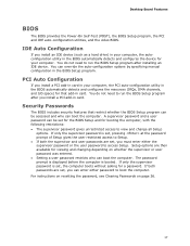
... the following restrictions: • The supervisor password gives unrestricted access to boot the computer. Desktop Board Features BIOS The BIOS provides the Power-On Self-Test (POST), the BIOS Setup program, the PCI and IDE auto-configuration utilities, and the video BIOS. PCI Auto Configuration If you install a PCI add-in card in card. Security Passwords...
... the following restrictions: • The supervisor password gives unrestricted access to boot the computer. Desktop Board Features BIOS The BIOS provides the Power-On Self-Test (POST), the BIOS Setup program, the PCI and IDE auto-configuration utilities, and the video BIOS. PCI Auto Configuration If you install a PCI add-in card in card. Security Passwords...
Product Guide
Page 21
... compliance required for using an antistatic wrist strap and a conductive foam pad. Follow these guidelines before you begin installing the Desktop Board: • Always follow the steps in each procedure in this chapter only at an ESD workstation using and modifying electronic ...I/O shield • Install and remove the Desktop Board • Install and remove memory • Connect the IDE cable • Connect the SATA cable • Connect internal headers • Connect chassis fan and power supply cables • Set the BIOS configuration and audio jumpers • Clear passwords ...
... compliance required for using an antistatic wrist strap and a conductive foam pad. Follow these guidelines before you begin installing the Desktop Board: • Always follow the steps in each procedure in this chapter only at an ESD workstation using and modifying electronic ...I/O shield • Install and remove the Desktop Board • Install and remove memory • Connect the IDE cable • Connect the SATA cable • Connect internal headers • Connect chassis fan and power supply cables • Set the BIOS configuration and audio jumpers • Clear passwords ...
Product Guide
Page 35
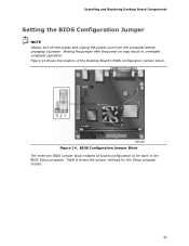
BIOS Configuration Jumper Block The three-pin BIOS jumper block enables all board configuration to be done in unreliable computer operation. Figure 14 shows the location of the Desktop Board's BIOS configuration jumper block. Table 8 shows the jumper settings for the Setup program modes. 35 Installing and Replacing Desktop Board Components Setting the BIOS Configuration Jumper NOTE Always turn off the power and unplug the power cord from the computer before changing a jumper. Moving the jumper with the power on may result in the BIOS Setup program. Figure 14.
BIOS Configuration Jumper Block The three-pin BIOS jumper block enables all board configuration to be done in unreliable computer operation. Figure 14 shows the location of the Desktop Board's BIOS configuration jumper block. Table 8 shows the jumper settings for the Setup program modes. 35 Installing and Replacing Desktop Board Components Setting the BIOS Configuration Jumper NOTE Always turn off the power and unplug the power cord from the computer before changing a jumper. Moving the jumper with the power on may result in the BIOS Setup program. Figure 14.
Product Guide
Page 36
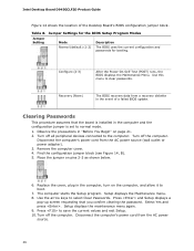
...arrow keys to save the current values and exit Setup. 10. Configure (2-3) After the Power-On Self-Test (POST) runs, the BIOS displays the Maintenance Menu. Disconnect the computer's power cord from the AC power source. 36 Use this menu to normal mode. 1. ... source (wall outlet or power adapter). 3. Replace the cover, plug in the event of the Desktop Board's BIOS configuration jumper block. Press and Setup displays a pop-up screen requesting that the board is set to clear passwords. Intel Desktop Board D945GCLF2D Product Guide Figure 14 shows the location of a failed...
...arrow keys to save the current values and exit Setup. 10. Configure (2-3) After the Power-On Self-Test (POST) runs, the BIOS displays the Maintenance Menu. Disconnect the computer's power cord from the AC power source. 36 Use this menu to normal mode. 1. ... source (wall outlet or power adapter). 3. Replace the cover, plug in the event of the Desktop Board's BIOS configuration jumper block. Press and Setup displays a pop-up screen requesting that the board is set to clear passwords. Intel Desktop Board D945GCLF2D Product Guide Figure 14 shows the location of a failed...

Product Guide
Page 37
...;ärä. Replacing the Battery A coin-cell battery (CR2032) powers the real-time clock and CMOS memory. VIKTIGT! Installing and Replacing Desktop Board Components 11. To restore normal operation, place the jumper on the computer. FORHOLDSREGEL Eksplosionsfare, hvis batteriet erstattes med et batteri af en forkert...supply extends the life of used batteries must be in the computer, and turn on pins 1-2 as shown below a certain level, the BIOS Setup program settings stored in CMOS RAM (for example, the date and time) might not be recycled where possible. Batterier bør om...
...;ärä. Replacing the Battery A coin-cell battery (CR2032) powers the real-time clock and CMOS memory. VIKTIGT! Installing and Replacing Desktop Board Components 11. To restore normal operation, place the jumper on the computer. FORHOLDSREGEL Eksplosionsfare, hvis batteriet erstattes med et batteri af en forkert...supply extends the life of used batteries must be in the computer, and turn on pins 1-2 as shown below a certain level, the BIOS Setup program settings stored in CMOS RAM (for example, the date and time) might not be recycled where possible. Batterier bør om...
Product Guide
Page 43
...Intel Desktop Board D945GCLF2D page, click "[view] Latest BIOS updates," and select the Express BIOS Update utility file. 3. Follow the instructions provided in an automated update utility that contains the files you are updating the BIOS for the computer. The Iflash BIOS update file contains: • New BIOS file • Intel... Flash Memory Update Utility 43 Navigate to http://support.intel.com/support/motherboards/desktop/. 2. This step is useful if you need to update the BIOS....
...Intel Desktop Board D945GCLF2D page, click "[view] Latest BIOS updates," and select the Express BIOS Update utility file. 3. Follow the instructions provided in an automated update utility that contains the files you are updating the BIOS for the computer. The Iflash BIOS update file contains: • New BIOS file • Intel... Flash Memory Update Utility 43 Navigate to http://support.intel.com/support/motherboards/desktop/. 2. This step is useful if you need to update the BIOS....
Product Guide
Page 44
... the process or the system may not function properly. 1. however, if an interruption occurs, the BIOS could be extracted locally to your computer supplier or by navigating to the Intel Desktop Board D945GCLF2D page at http://support.intel.com/support/motherboards/desktop. Intel Desktop Board D945GCLF2D Product Guide You can be damaged. The Iflash Memory update utility allows you can update the...
... the process or the system may not function properly. 1. however, if an interruption occurs, the BIOS could be extracted locally to your computer supplier or by navigating to the Intel Desktop Board D945GCLF2D page at http://support.intel.com/support/motherboards/desktop. Intel Desktop Board D945GCLF2D Product Guide You can be damaged. The Iflash Memory update utility allows you can update the...
Product Guide
Page 45
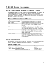
... Power LED Blink Codes Type Processor initialization complete POST complete BIOS update in Table 10. repeat entire pattern (four on-off blinks and 3-second pause) until system is complete. In addition, whenever a recoverable error occurs during POST, the BIOS causes the front-panel power ... second, then off for 0.5 second when processor initialization is powered off Thermal warning On-off (0.5 second each) four times, then 3.0 second pause (off) between on-off blink pattern; pattern repeats until system is used by the BIOS to the board's line out jack (see Table 9). These...
... Power LED Blink Codes Type Processor initialization complete POST complete BIOS update in Table 10. repeat entire pattern (four on-off blinks and 3-second pause) until system is complete. In addition, whenever a recoverable error occurs during POST, the BIOS causes the front-panel power ... second, then off for 0.5 second when processor initialization is powered off Thermal warning On-off (0.5 second each) four times, then 3.0 second pause (off) between on-off blink pattern; pattern repeats until system is used by the BIOS to the board's line out jack (see Table 9). These...
Product Guide
Page 46
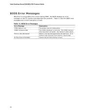
.... Run Setup to boot. 46 System did not find a device to reset values. Intel Desktop Board D945GCLF2D Product Guide BIOS Error Messages Whenever a recoverable error occurs during POST, the BIOS displays an error message on the PC monitor that describes the problem. BIOS Error Messages Error Message CMOS Battery Low CMOS Checksum Bad Memory Size Decreased No...
.... Run Setup to boot. 46 System did not find a device to reset values. Intel Desktop Board D945GCLF2D Product Guide BIOS Error Messages Whenever a recoverable error occurs during POST, the BIOS displays an error message on the PC monitor that describes the problem. BIOS Error Messages Error Message CMOS Battery Low CMOS Checksum Bad Memory Size Decreased No...


