
Product Specification
Page 24
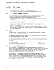
..., noise, and inductive coupling. For compatibility, the underlying Serial ATA functionality is similar to 66 MB/sec. Native mode is device driver compatible. • ATA-100: DMA protocol... port. In legacy mode, standard IDE I /O (PIO): processor controls data transfer. • 8237-style DMA: DMA offloads the processor, supporting transfer rates of up to 16 MB/sec. •...BIOS. In Native mode, standard PCI Conventional bus resource steering is used . Intel Desktop Board D945GCCR Technical Product Specification 1.5.3 IDE Support The board provides five IDE interface connectors: &#...
..., noise, and inductive coupling. For compatibility, the underlying Serial ATA functionality is similar to 66 MB/sec. Native mode is device driver compatible. • ATA-100: DMA protocol... port. In legacy mode, standard IDE I /O (PIO): processor controls data transfer. • 8237-style DMA: DMA offloads the processor, supporting transfer rates of up to 16 MB/sec. •...BIOS. In Native mode, standard PCI Conventional bus resource steering is used . Intel Desktop Board D945GCCR Technical Product Specification 1.5.3 IDE Support The board provides five IDE interface connectors: &#...

Product Specification
Page 31
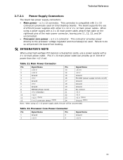
...as needed • SMBus interface For information about The functions of monitoring and control is dependent on the chassis that can be compatible with the board. When the chassis cover is removed, the mechanical switch is in the closed -loop fan control, for all... monitoring and fan control ASIC include: • Internal ambient temperature sensor • Two remote thermal diode sensors for direct monitoring of processor temperature and ambient temperature sensing • Power supply monitoring of the fan headers and sensors for Management (WfM) specification. Product Description ...
...as needed • SMBus interface For information about The functions of monitoring and control is dependent on the chassis that can be compatible with the board. When the chassis cover is removed, the mechanical switch is in the closed -loop fan control, for all... monitoring and fan control ASIC include: • Internal ambient temperature sensor • Two remote thermal diode sensors for direct monitoring of processor temperature and ambient temperature sensing • Power supply monitoring of the fan headers and sensors for Management (WfM) specification. Product Description ...
Product Specification
Page 53
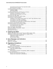
Table 21. This connector is compatible with a 2 x 10 main power cable, attach that cable on the rightmost pins of the main power connector, leaving pins 11, 12, 23, and 24 unconnected. • Processor core power - a 2 x 2 connector. When using a power supply with 2 x 10 connectors previously...1 +3.3 V 13 +3.3 V 2 +3.3 V 14 -12 V 3 Ground 15 Ground 4 +5 V 16 PS-ON# (power supply remote on Intel Desktop boards. Technical Reference 2.7.2.1 Power Supply Connectors The board has power supply connectors: • Main power - The board supports the use a power ...
Table 21. This connector is compatible with a 2 x 10 main power cable, attach that cable on the rightmost pins of the main power connector, leaving pins 11, 12, 23, and 24 unconnected. • Processor core power - a 2 x 2 connector. When using a power supply with 2 x 10 connectors previously...1 +3.3 V 13 +3.3 V 2 +3.3 V 14 -12 V 3 Ground 15 Ground 4 +5 V 16 PS-ON# (power supply remote on Intel Desktop boards. Technical Reference 2.7.2.1 Power Supply Connectors The board has power supply connectors: • Main power - The board supports the use a power ...

Product Specification
Page 71
... of the high capacities typically available today, hard drives are required: • An ATA-66/100 peripheral device • An ATA-66/100 compatible cable • ATA-66/100 operating system device drivers NOTE Do not connect an ATA device as a slave on the same IDE cable as a...level • Fixed-system data, such as peripherals, serial numbers, and asset tags • Resource data, such as memory size, cache size, and processor speed • Dynamic data, such as event detection and error logging Non-Plug and Play operating systems, such as third-party management software to use...
... of the high capacities typically available today, hard drives are required: • An ATA-66/100 peripheral device • An ATA-66/100 compatible cable • ATA-66/100 operating system device drivers NOTE Do not connect an ATA device as a slave on the same IDE cable as a...level • Fixed-system data, such as peripherals, serial numbers, and asset tags • Resource data, such as memory size, cache size, and processor speed • Dynamic data, such as event detection and error logging Non-Plug and Play operating systems, such as third-party management software to use...
Intel Desktop Board D945GCCR Product Guide English
Page 6
Intel Desktop Board D945GCCR Product Guide Connecting the Processor Fan Heat Sink Cable 34 Removing the Processor 34 Installing and Removing Memory 35 Installing DIMMs 37 Removing DIMMs 38 Installing and Removing a PCI Express x16 Card 39 Installing a PCI Express x16 Card... Battery Marking 65 European Union Declaration of Conformity Statement 66 Product Ecology Statements 67 Lead-Free Desktop Board 70 EMC Regulations 71 Ensure Electromagnetic Compatibility (EMC) Compliance 72 Product Certifications 73 Board-Level Certification Markings 73 Chassis and Component Certifications 74 vi
Intel Desktop Board D945GCCR Product Guide Connecting the Processor Fan Heat Sink Cable 34 Removing the Processor 34 Installing and Removing Memory 35 Installing DIMMs 37 Removing DIMMs 38 Installing and Removing a PCI Express x16 Card 39 Installing a PCI Express x16 Card... Battery Marking 65 European Union Declaration of Conformity Statement 66 Product Ecology Statements 67 Lead-Free Desktop Board 70 EMC Regulations 71 Ensure Electromagnetic Compatibility (EMC) Compliance 72 Product Certifications 73 Board-Level Certification Markings 73 Chassis and Component Certifications 74 vi

Intel Desktop Board D945GCCR Product Guide English
Page 19
... Passwords The BIOS includes security features that restrict whether the BIOS Setup program can be compatible with the Wired for Management (WfM) specification. Setup options are then available for viewing... not need to detect levels above and below acceptable values • Intel Precision Cooling Technology • Thermal sensors in the processor, GMCH, and ICH7 plus an onboard remote sensor • Thermally.... If only the supervisor password is set, pressing at the password prompt of Desktop Board D945GCCR enable the board to view and change all onboard fans, that add-in card. If ...
... Passwords The BIOS includes security features that restrict whether the BIOS Setup program can be compatible with the Wired for Management (WfM) specification. Setup options are then available for viewing... not need to detect levels above and below acceptable values • Intel Precision Cooling Technology • Thermal sensors in the processor, GMCH, and ICH7 plus an onboard remote sensor • Thermally.... If only the supervisor password is set, pressing at the password prompt of Desktop Board D945GCCR enable the board to view and change all onboard fans, that add-in card. If ...
Intel Desktop Board D945GCCR Product Guide English
Page 49
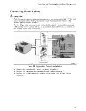
... and/or not connecting the 12 V (2 x 2 pin) power connector to the desktop board may result in "Before You Begin" on the desktop board is backwards compatible with ATX12V power supplies with 2 x 10 connectors. Connect the main power supply cable to the board or the system may not function properly. The 2 x 12... pin main power connector on page 25. 2. Figure 23 shows the location of the desktop board power connectors. Connect the 12 V processor core voltage power supply cable to the 2 x 2 pin connector. 49 Figure 23.
... and/or not connecting the 12 V (2 x 2 pin) power connector to the desktop board may result in "Before You Begin" on the desktop board is backwards compatible with ATX12V power supplies with 2 x 10 connectors. Connect the main power supply cable to the board or the system may not function properly. The 2 x 12... pin main power connector on page 25. 2. Figure 23 shows the location of the desktop board power connectors. Connect the 12 V processor core voltage power supply cable to the 2 x 2 pin connector. 49 Figure 23.


