

Product Specification
Page 2
... for conflicts or incompatibilities arising from published specifications. Contact your local Intel sales office or your distributor to only the standard Intel Desktop Board D945GCCR with BIOS identifier CR94510J.86A. Intel, the Intel logo, Pentium, Intel Core 2 Duo, and Celeron are referenced in the Intel Desktop Board D945GCCR Specification Update before placing your product order. INFORMATION IN THIS DOCUMENT...
... for conflicts or incompatibilities arising from published specifications. Contact your local Intel sales office or your distributor to only the standard Intel Desktop Board D945GCCR with BIOS identifier CR94510J.86A. Intel, the Intel logo, Pentium, Intel Core 2 Duo, and Celeron are referenced in the Intel Desktop Board D945GCCR Specification Update before placing your product order. INFORMATION IN THIS DOCUMENT...
Product Specification
Page 3
... not intended for the Intel® Desktop Board D945GCCR. What This Document Contains Chapter 1 2 3 4 5 Description A description of the hardware used on the Desktop Board D945GCCR A map of the resources of the Desktop Board The features supported by the BIOS Setup program A description ... general audiences. Not all of the BIOS error messages, beep codes, and POST codes Regulatory compliance and battery disposal information Typographical Conventions This section contains information about the Desktop Board D945GCCR and its components to system integrators. Notes, Cautions, and ...
... not intended for the Intel® Desktop Board D945GCCR. What This Document Contains Chapter 1 2 3 4 5 Description A description of the hardware used on the Desktop Board D945GCCR A map of the resources of the Desktop Board The features supported by the BIOS Setup program A description ... general audiences. Not all of the BIOS error messages, beep codes, and POST codes Regulatory compliance and battery disposal information Typographical Conventions This section contains information about the Desktop Board D945GCCR and its components to system integrators. Notes, Cautions, and ...
Product Specification
Page 6
Intel Desktop Board D945GCCR Technical Product Specification 2.5 Interrupts 46 2.6 PCI Conventional Interrupt Routing Map 47 2.7 Connectors and Headers 48 2.7.1 Back Panel Connectors 49 2.7.2 Component-... 2.11 Thermal Considerations 64 2.12 Reliability 66 2.13 Environmental 67 3 Overview of BIOS Features 3.1 Introduction 69 3.2 BIOS Flash Memory Organization 70 3.3 Resource Configuration 70 3.3.1 PCI Autoconfiguration 70 3.3.2 PCI IDE Support 71 3.4 System Management BIOS (SMBIOS 71 3.5 BIOS Updates 72 3.5.1 Language Support 72 3.5.2 Custom Splash Screen 72 3.6 Legacy USB Support...
Intel Desktop Board D945GCCR Technical Product Specification 2.5 Interrupts 46 2.6 PCI Conventional Interrupt Routing Map 47 2.7 Connectors and Headers 48 2.7.1 Back Panel Connectors 49 2.7.2 Component-... 2.11 Thermal Considerations 64 2.12 Reliability 66 2.13 Environmental 67 3 Overview of BIOS Features 3.1 Introduction 69 3.2 BIOS Flash Memory Organization 70 3.3 Resource Configuration 70 3.3.1 PCI Autoconfiguration 70 3.3.2 PCI IDE Support 71 3.4 System Management BIOS (SMBIOS 71 3.5 BIOS Updates 72 3.5.1 Language Support 72 3.5.2 Custom Splash Screen 72 3.6 Legacy USB Support...
Product Specification
Page 8
... 19. Auxiliary Front Panel Power/Sleep LED Header 54 24. States for Components 66 31. BIOS Setup Program Function Keys 70 34. Typical Port 80h POST Sequence 82 41. Product Certification Markings 90 viii Intel Desktop Board D945GCCR Technical Product Specification 15. Processor Core Power Connector 53 23. States for a Two-Color Power...
... 19. Auxiliary Front Panel Power/Sleep LED Header 54 24. States for Components 66 31. BIOS Setup Program Function Keys 70 34. Typical Port 80h POST Sequence 82 41. Product Certification Markings 90 viii Intel Desktop Board D945GCCR Technical Product Specification 15. Processor Core Power Connector 53 23. States for a Two-Color Power...
Product Specification
Page 10
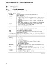
... D945GCCR Technical Product Specification 1.1 Overview 1.1.1 Feature Summary Table 1 summarizes the major features of : • Intel® 82945GC Graphics Memory Controller Hub (GMCH) • Intel® 82801GB I/O Controller Hub (ICH7) Intel® GMA950 onboard graphics subsystem 6-channel (5.1) audio subsystem with three analog audio outputs using the Intel® 82562G Platform LAN Connect (PLC) device • Intel® BIOS...
... D945GCCR Technical Product Specification 1.1 Overview 1.1.1 Feature Summary Table 1 summarizes the major features of : • Intel® 82945GC Graphics Memory Controller Hub (GMCH) • Intel® 82801GB I/O Controller Hub (ICH7) Intel® GMA950 onboard graphics subsystem 6-channel (5.1) audio subsystem with three analog audio outputs using the Intel® 82562G Platform LAN Connect (PLC) device • Intel® BIOS...
Product Specification
Page 13
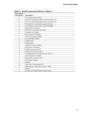
... core power connector H Processor fan header I Rear chassis fan header J LGA775 processor socket K Intel 82945GC GMCH L DIMM socket M DIMM socket N Chassis intrusion header O Main Power connector P Diskette drive connector Q Parallel ATE ...IDE connector R Intel 82801GB I/O Controller Hub (ICH7) S Front chassis fan header T Serial ATA connectors [4] U Front panel header V Speaker W Front panel USB headers [2] X BIOS Setup configuration jumper block Y Battery Z Auxiliary front panel power LED ...
... core power connector H Processor fan header I Rear chassis fan header J LGA775 processor socket K Intel 82945GC GMCH L DIMM socket M DIMM socket N Chassis intrusion header O Main Power connector P Diskette drive connector Q Parallel ATE ...IDE connector R Intel 82801GB I/O Controller Hub (ICH7) S Front chassis fan header T Serial ATA connectors [4] U Front panel header V Speaker W Front panel USB headers [2] X BIOS Setup configuration jumper block Y Battery Z Auxiliary front panel power LED ...
Product Specification
Page 16
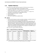
This allows the BIOS to read the SPD data and program the chipset to avoid interference with the memory retention mechanism. • To be fully compliant with all applicable ... are not supported. • 2 GB maximum total system memory. If nonSPD memory is installed, the BIOS will attempt to Section 2.1.1 on page 41 for optimum performance. Table 3. Table 3 lists the supported DIMM configurations. Intel Desktop Board D945GCCR Technical Product Specification 1.4 System Memory The board has two DIMM sockets and supports the following memory...
This allows the BIOS to read the SPD data and program the chipset to avoid interference with the memory retention mechanism. • To be fully compliant with all applicable ... are not supported. • 2 GB maximum total system memory. If nonSPD memory is installed, the BIOS will attempt to Section 2.1.1 on page 41 for optimum performance. Table 3. Table 3 lists the supported DIMM configurations. Intel Desktop Board D945GCCR Technical Product Specification 1.4 System Memory The board has two DIMM sockets and supports the following memory...

Product Specification
Page 22
...memory utilization. DVMT ensures the most efficient use a minimal fixed portion of system physical memory (as needed for performing graphics functions. Intel Desktop Board D945GCCR Technical Product Specification • Video ⎯ Hardware motion compensation for MPEG2 ⎯ Software DVD at 30 fps full screen •... ⎯ DDC2B compliant interface with Advanced Digital Display 2 or 2+ (ADD2/ADD2+) cards, support for TV-out/TV-in the BIOS Setup program) for compatibility with 200 MHz pixel clocks using VGA graphics under DOS. DVMT will always use of system memory can be...
...memory utilization. DVMT ensures the most efficient use a minimal fixed portion of system physical memory (as needed for performing graphics functions. Intel Desktop Board D945GCCR Technical Product Specification • Video ⎯ Hardware motion compensation for MPEG2 ⎯ Software DVD at 30 fps full screen •... ⎯ DDC2B compliant interface with Advanced Digital Display 2 or 2+ (ADD2/ADD2+) cards, support for TV-out/TV-in the BIOS Setup program) for compatibility with 200 MHz pixel clocks using VGA graphics under DOS. DVMT will always use of system memory can be...
Product Specification
Page 24
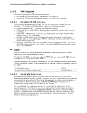
...also supports ATAPI devices (such as CD-ROM drives) and ATA devices using the Windows* XP and Windows 2000 operating systems. 24 The BIOS supports Logical Block Addressing (LBA) and Extended Cylinder Head Sector (ECHS) translation modes. In legacy mode, standard IDE I /O (PIO... modes. In Native mode, standard PCI Conventional bus resource steering is transparent to reduce reflections, noise, and inductive coupling. Intel Desktop Board D945GCCR Technical Product Specification 1.5.3 IDE Support The board provides five IDE interface connectors: • One parallel ATA IDE connector that ...
...also supports ATAPI devices (such as CD-ROM drives) and ATA devices using the Windows* XP and Windows 2000 operating systems. 24 The BIOS supports Logical Block Addressing (LBA) and Extended Cylinder Head Sector (ECHS) translation modes. In legacy mode, standard IDE I /O (PIO... modes. In Native mode, standard PCI Conventional bus resource steering is transparent to reduce reflections, noise, and inductive coupling. Intel Desktop Board D945GCCR Technical Product Specification 1.5.3 IDE Support The board provides five IDE interface connectors: • One parallel ATA IDE connector that ...
Product Specification
Page 26
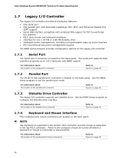
... to set the parallel port mode. Intel Desktop Board D945GCCR Technical Product Specification 1.7 Legacy I/O Controller The legacy I/O controller provides the following features: • One serial port • One parallel port with Extended Capabilities Port (ECP) and Enhanced Parallel Port (EPP) support • Serial IRQ interface compatible with BIOS support. For information about The...
... to set the parallel port mode. Intel Desktop Board D945GCCR Technical Product Specification 1.7 Legacy I/O Controller The legacy I/O controller provides the following features: • One serial port • One parallel port with Extended Capabilities Port (ECP) and Enhanced Parallel Port (EPP) support • Serial IRQ interface compatible with BIOS support. For information about The...

Product Specification
Page 35
... to Power On will enable a wake-up the computer... Wake-up Devices and Events These devices/events can wake up event from LAN in the BIOS Setup program. The board provides several power management hardware features, including: • Power connector • Fan headers • LAN wake capabilities • Instantly Available PC...
... to Power On will enable a wake-up the computer... Wake-up Devices and Events These devices/events can wake up event from LAN in the BIOS Setup program. The board provides several power management hardware features, including: • Power connector • Fan headers • LAN wake capabilities • Instantly Available PC...

Product Specification
Page 36
... the fan headers is as needed. • All fan headers have a +12 V DC connection. Intel Desktop Board D945GCCR Technical Product Specification Resume on Ring enables telephony devices to the power state it is off or in the BIOS Setup program's Boot menu. For information about The location of the fan headers The location...
... the fan headers is as needed. • All fan headers have a +12 V DC connection. Intel Desktop Board D945GCCR Technical Product Specification Resume on Ring enables telephony devices to the power state it is off or in the BIOS Setup program's Boot menu. For information about The location of the fan headers The location...
Product Specification
Page 38
Intel Desktop Board D945GCCR Technical Product Specification 1.11.2.6 Wake from USB USB bus activity wakes the computer from an ACPI S1, S3, S4, or S5 state. 38 NOTE Wake ... on the PCI Conventional bus is asserted, the computer wakes from an ACPI S1, S3, S4, or S5 state (with Wake on PME enabled in BIOS). 1.11.2.9 WAKE# Signal Wake-up Support When the WAKE# signal on the PCI Express bus is asserted, the computer wakes from ACPI S1 or S3...
Intel Desktop Board D945GCCR Technical Product Specification 1.11.2.6 Wake from USB USB bus activity wakes the computer from an ACPI S1, S3, S4, or S5 state. 38 NOTE Wake ... on the PCI Conventional bus is asserted, the computer wakes from an ACPI S1, S3, S4, or S5 state (with Wake on PME enabled in BIOS). 1.11.2.9 WAKE# Signal Wake-up Support When the WAKE# signal on the PCI Express bus is asserted, the computer wakes from ACPI S1 or S3...
Product Specification
Page 41
... that has 2 GB of system memory installed, it is not possible to use all of DRAM (total system memory). These functions include the following: • BIOS/ SPI Flash (4 MB) • Local APIC (19 MB) • Digital Media Interface (40 MB) • Front side bus interrupts (17 MB) ... 41 2.2 DMA Channels 43 2.3 Fixed I /O that is dynamically allocated for PCI Conventional and PCI Express add-in cards, PCI Express configuration space, BIOS (SPI Flash), and chipset overhead resides above the top of the installed memory due to system address space being allocated for PCI Conventional bus add...
... that has 2 GB of system memory installed, it is not possible to use all of DRAM (total system memory). These functions include the following: • BIOS/ SPI Flash (4 MB) • Local APIC (19 MB) • Digital Media Interface (40 MB) • Front side bus interrupts (17 MB) ... 41 2.2 DMA Channels 43 2.3 Fixed I /O that is dynamically allocated for PCI Conventional and PCI Express add-in cards, PCI Express configuration space, BIOS (SPI Flash), and chipset overhead resides above the top of the installed memory due to system address space being allocated for PCI Conventional bus add...
Product Specification
Page 42
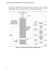
All installed system memory can be used will vary based on add-in cards and BIOS settings. Figure 11. Intel Desktop Board D945GCCR Technical Product Specification The amount of installed memory that can be used when there is no overlap of the system memory map. Figure 11 shows a schematic of system addresses. Detailed System Memory Address Map 42
All installed system memory can be used will vary based on add-in cards and BIOS settings. Figure 11. Intel Desktop Board D945GCCR Technical Product Specification The amount of installed memory that can be used when there is no overlap of the system memory map. Figure 11 shows a schematic of system addresses. Detailed System Memory Address Map 42
Product Specification
Page 43
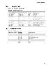
EFFFF 800 K - 896 K C8000 - Video memory and BIOS Extended BIOS data (movable by memory manager software) Extended conventional memory Conventional memory 2.2 DMA Channels Table 10. System Memory Map Address Range (decimal) Address Range (hex) 1024 K - ... - 9FFFF 80000 - 9FBFF 00000 - 7FFFF Size 2048 MB 64 KB 64 KB 96 KB 160 KB 1 KB 127 KB 512 KB Description Extended memory Runtime BIOS Reserved Potential available high DOS memory (open to the PCI Conventional bus). FFFFFFFF 960 K - 1024 K F0000 - FFFFF 896 K - 960 K E0000 - Dependent on video adapter used...
EFFFF 800 K - 896 K C8000 - Video memory and BIOS Extended BIOS data (movable by memory manager software) Extended conventional memory Conventional memory 2.2 DMA Channels Table 10. System Memory Map Address Range (decimal) Address Range (hex) 1024 K - ... - 9FFFF 80000 - 9FBFF 00000 - 7FFFF Size 2048 MB 64 KB 64 KB 96 KB 160 KB 1 KB 127 KB 512 KB Description Extended memory Runtime BIOS Reserved Potential available high DOS memory (open to the PCI Conventional bus). FFFFFFFF 960 K - 1024 K F0000 - FFFFF 896 K - 960 K E0000 - Dependent on video adapter used...
Product Specification
Page 58
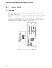
...Jumper Block 58 When the jumper is set to configure mode and the computer is powered-up, the BIOS compares the processor version and the microcode version in the BIOS and reports if the two match. Location of the jumper block. Always turn off the power and unplug... cord from the computer before changing a jumper setting. Otherwise, the board could be damaged. The jumper block determines the BIOS Setup program's mode. Figure 16. Intel Desktop Board D945GCCR Technical Product Specification 2.8 Jumper Block CAUTION Do not move the jumper with the power on. Table 27 describes the jumper...
...Jumper Block 58 When the jumper is set to configure mode and the computer is powered-up, the BIOS compares the processor version and the microcode version in the BIOS and reports if the two match. Location of the jumper block. Always turn off the power and unplug... cord from the computer before changing a jumper setting. Otherwise, the board could be damaged. The jumper block determines the BIOS Setup program's mode. Figure 16. Intel Desktop Board D945GCCR Technical Product Specification 2.8 Jumper Block CAUTION Do not move the jumper with the power on. Table 27 describes the jumper...
Product Specification
Page 59
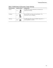
Configure 2-3 321 After the POST runs, Setup runs automatically. Recovery 321 None 321 The BIOS attempts to recover the BIOS configuration. The maintenance menu is required. 59 BIOS Setup Configuration Jumper Settings Function/Mode Normal Jumper Setting 1-2 Configuration The BIOS uses current configuration information and passwords for booting. Technical Reference Table 27. A recovery diskette is displayed.
Configure 2-3 321 After the POST runs, Setup runs automatically. Recovery 321 None 321 The BIOS attempts to recover the BIOS configuration. The maintenance menu is required. 59 BIOS Setup Configuration Jumper Settings Function/Mode Normal Jumper Setting 1-2 Configuration The BIOS uses current configuration information and passwords for booting. Technical Reference Table 27. A recovery diskette is displayed.

Product Specification
Page 69
... Support 73 3.7 Boot Options 73 3.8 Adjusting Boot Speed 75 3.9 BIOS Security Features 76 3.1 Introduction The boards use an Intel BIOS that is stored in configure mode. When the BIOS Setup configuration jumper is set to view and change the BIOS settings for the computer. The BIOS Setup program can be used to configure mode and the...
... Support 73 3.7 Boot Options 73 3.8 Adjusting Boot Speed 75 3.9 BIOS Security Features 76 3.1 Introduction The boards use an Intel BIOS that is stored in configure mode. When the BIOS Setup configuration jumper is set to view and change the BIOS settings for the computer. The BIOS Setup program can be used to configure mode and the...
Product Specification
Page 70
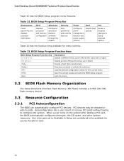
... system resources. Table 33. Autoconfiguration lets a user insert or remove PCI cards without having to be onboard or add-in card. 70 BIOS Setup Program Function Keys BIOS Setup Program Function Key or or Description Selects a different menu screen (Moves the cursor left or right) Selects an item (Moves the ... interrupts set to Available in Setup are considered to configure the system. PCI devices may be available for use by the add-in cards. Intel Desktop Board D945GCCR Technical Product Specification Table 32 lists the BIOS Setup program menu features. Table 32.
... system resources. Table 33. Autoconfiguration lets a user insert or remove PCI cards without having to be onboard or add-in card. 70 BIOS Setup Program Function Keys BIOS Setup Program Function Key or or Description Selects a different menu screen (Moves the cursor left or right) Selects an item (Moves the ... interrupts set to Available in Setup are considered to configure the system. PCI devices may be available for use by the add-in cards. Intel Desktop Board D945GCCR Technical Product Specification Table 32 lists the BIOS Setup program menu features. Table 32.


