

Product Specification
Page 1
Current characterized errata are documented in the Intel Desktop Boards D925XECV2/D925XEBC2 Specification Update. Intel® Desktop Boards D925XECV2/D925XEBC2 Technical Product Specification October 2004 Order Number: C90152-001 The Intel® Desktop Boards D925XECV2/D925XEBC2 may contain design defects or errors known as errata that may cause the product to deviate from published specifications.
Current characterized errata are documented in the Intel Desktop Boards D925XECV2/D925XEBC2 Specification Update. Intel® Desktop Boards D925XECV2/D925XEBC2 Technical Product Specification October 2004 Order Number: C90152-001 The Intel® Desktop Boards D925XECV2/D925XEBC2 may contain design defects or errors known as errata that may cause the product to deviate from published specifications.

Product Specification
Page 2
... placing your distributor to any such patents, trademarks, copyrights, or other Countries 708-296-9333. Changes to only standard Intel® Desktop Boards D925XECV2 and D925XEBC2 with BIOS identifier CV92510A.86A. Copyright © 2004, Intel Corporation. Intel may contain design defects or errors known as the property of others. Designers must not rely on request...
... placing your distributor to any such patents, trademarks, copyrights, or other Countries 708-296-9333. Changes to only standard Intel® Desktop Boards D925XECV2 and D925XEBC2 with BIOS identifier CV92510A.86A. Copyright © 2004, Intel Corporation. Intel may contain design defects or errors known as the property of others. Designers must not rely on request...
Product Specification
Page 3
... for general audiences. What This Document Contains Chapter 1 2 3 4 Description A description of the hardware used on the Desktop Boards D925XECV2 and D925XEBC2 A map of the resources of the Desktop Boards The features supported by the BIOS Setup program A description of the BIOS error messages... to the vendors, system integrators, and other engineers and technicians who need this level of these Intel® Desktop Boards: D925XECV2 and D925XEBC2. It describes the standard product and available manufacturing options. Intended Audience The TPS is specifically not intended...
... for general audiences. What This Document Contains Chapter 1 2 3 4 Description A description of the hardware used on the Desktop Boards D925XECV2 and D925XEBC2 A map of the resources of the Desktop Boards The features supported by the BIOS Setup program A description of the BIOS error messages... to the vendors, system integrators, and other engineers and technicians who need this level of these Intel® Desktop Boards: D925XECV2 and D925XEBC2. It describes the standard product and available manufacturing options. Intended Audience The TPS is specifically not intended...
Product Specification
Page 4
... Mbit Mbit/sec xxh x.x V * Used after a signal name to indicate third-party brands and names that general location. Intel Desktop Boards D925XECV2/D925XEBC2 Technical Product Specification WARNING Warnings indicate conditions, which if not observed, can cause personal injury. Gigabyte (1,073,741,824 bytes) ... data value ending with a lowercase h indicates a hexadecimal value. iv Voltages are the property of its location on the Desktop Boards D925XECV2 and D925XEBC2, and X is a connector, located at 5J. Volts. For example, J5J1 is the instance of the particular part at that ...
... Mbit Mbit/sec xxh x.x V * Used after a signal name to indicate third-party brands and names that general location. Intel Desktop Boards D925XECV2/D925XEBC2 Technical Product Specification WARNING Warnings indicate conditions, which if not observed, can cause personal injury. Gigabyte (1,073,741,824 bytes) ... data value ending with a lowercase h indicates a hexadecimal value. iv Voltages are the property of its location on the Desktop Boards D925XECV2 and D925XEBC2, and X is a connector, located at 5J. Volts. For example, J5J1 is the instance of the particular part at that ...
Product Specification
Page 6
Intel Desktop Boards D925XECV2/D925XEBC2 Technical Product Specification 1.15 Trusted Platform Module (Optional 47 1.15.1 System Requirements 47 1.15.2 Warning of Potential Data Loss 47 1.15.3 Security Precautions 48 1....Interrupt Routing Map 61 2.8 Connectors...63 2.8.1 Back Panel Connectors 63 2.8.2 Component-side Connectors 68 2.9 Jumper Block ...80 2.10 Mechanical Considerations 81 2.10.1 D925XECV2 Form Factor 81 2.10.2 D925XEBC2 Form Factor 82 2.10.3 I/O Shield...83 2.11 Electrical Considerations 85 2.11.1 DC Loading...85 2.11.2 Add-in Board Considerations 85 2.11.3 Fan ...
Intel Desktop Boards D925XECV2/D925XEBC2 Technical Product Specification 1.15 Trusted Platform Module (Optional 47 1.15.1 System Requirements 47 1.15.2 Warning of Potential Data Loss 47 1.15.3 Security Precautions 48 1....Interrupt Routing Map 61 2.8 Connectors...63 2.8.1 Back Panel Connectors 63 2.8.2 Component-side Connectors 68 2.9 Jumper Block ...80 2.10 Mechanical Considerations 81 2.10.1 D925XECV2 Form Factor 81 2.10.2 D925XEBC2 Form Factor 82 2.10.3 I/O Shield...83 2.11 Electrical Considerations 85 2.11.1 DC Loading...85 2.11.2 Add-in Board Considerations 85 2.11.3 Fan ...

Product Specification
Page 7
...Systems with Four DIMMs 23 8. Contents 3 Overview of the Standby Power Indicator LED on the D925XECV2 Board 46 18. Front/Back Panel Audio Connector Options for D925XEBC2 Board 39 17. Back Panel Connectors for 8-Channel (7.1) Audio Subsystem 64 vii LAN Connector LED ... Mode Configuration with Three DIMMs 22 7. Block Diagram...18 4. Dual Channel (Interleaved) Mode Configuration with Intel® Rapid BIOS Boot 100 3.8.1 Peripheral Selection and Configuration 100 3.8.2 Intel Rapid BIOS Boot 100 3.9 BIOS Security Features 101 4 Error Messages and Beep Codes 4.1 BIOS Error ...
...Systems with Four DIMMs 23 8. Contents 3 Overview of the Standby Power Indicator LED on the D925XECV2 Board 46 18. Front/Back Panel Audio Connector Options for D925XEBC2 Board 39 17. Back Panel Connectors for 8-Channel (7.1) Audio Subsystem 64 vii LAN Connector LED ... Mode Configuration with Three DIMMs 22 7. Block Diagram...18 4. Dual Channel (Interleaved) Mode Configuration with Intel® Rapid BIOS Boot 100 3.8.1 Peripheral Selection and Configuration 100 3.8.2 Intel Rapid BIOS Boot 100 3.9 BIOS Security Features 101 4 Error Messages and Beep Codes 4.1 BIOS Error ...
Product Specification
Page 8
Intel Desktop Boards D925XECV2/D925XEBC2 Technical Product Specification 20. Connection Diagram for Front Panel Connector 77 24. Location of Board Differences 11 2. Summary of the Jumper Block 80 27. Feature ... Map 57 12. Main Power Connector 75 30. States for Omni-directional Airflow 87 32. D925XECV2 Component-side Connectors 68 22. Connection Diagram for 6-Channel (5.1) Audio Subsystem 66 21. Back Panel Connectors Shown in Figure 2 17 6. D925XEBC2 Component-side Connectors 70 23. I /O Map ...58 14. Front Panel Audio Connector 72 23. Back...
Intel Desktop Boards D925XECV2/D925XEBC2 Technical Product Specification 20. Connection Diagram for Front Panel Connector 77 24. Location of Board Differences 11 2. Summary of the Jumper Block 80 27. Feature ... Map 57 12. Main Power Connector 75 30. States for Omni-directional Airflow 87 32. D925XECV2 Component-side Connectors 68 22. Connection Diagram for 6-Channel (5.1) Audio Subsystem 66 21. Back Panel Connectors Shown in Figure 2 17 6. D925XEBC2 Component-side Connectors 70 23. I /O Map ...58 14. Front Panel Audio Connector 72 23. Back...
Product Specification
Page 9
.... BIOS Setup Program Function Keys 96 46. Safety Regulations ...91 42. Boot Device Menu Options 99 47. Fan Connector Current Capability 86 39. Desktop Board D925XECV2/D925XEBC2 Environmental Specifications 90 41. EMC Regulations ...91 43. Boot Block Recovery Code Checkpoints 105 51. Lower Nibble High Byte Functions 110 55. Beep Codes ...110...
.... BIOS Setup Program Function Keys 96 46. Safety Regulations ...91 42. Boot Device Menu Options 99 47. Fan Connector Current Capability 86 39. Desktop Board D925XECV2/D925XEBC2 Environmental Specifications 90 41. EMC Regulations ...91 43. Boot Block Recovery Code Checkpoints 105 51. Lower Nibble High Byte Functions 110 55. Beep Codes ...110...
Product Specification
Page 11
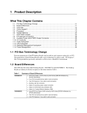
This generation of Intel Desktop Boards adds a new technology for Trusted Platform Module (TPM) D925XEBC2 • microATX Form Factor (9.60 ...identical with the exception of the items listed in cards: PCI Express*. Summary of Board Differences D925XECV2 • ATX Form Factor (10.20 inches by 9.60 inches [259.08 millimeters by ...11 1.2 Board Differences ...11 1.3 Overview ...12 1.4 Online Support ...19 1.5 Processor ...19 1.6 System Memory ...20 1.7 Intel® 925X Chipset...25 1.8 PCI Express Connectors 28 1.9 Auxiliary Power (AUX PWR) Output Connector 28 1.10 I/O Controller......
This generation of Intel Desktop Boards adds a new technology for Trusted Platform Module (TPM) D925XEBC2 • microATX Form Factor (9.60 ...identical with the exception of the items listed in cards: PCI Express*. Summary of Board Differences D925XECV2 • ATX Form Factor (10.20 inches by 9.60 inches [259.08 millimeters by ...11 1.2 Board Differences ...11 1.3 Overview ...12 1.4 Online Support ...19 1.5 Processor ...19 1.6 System Memory ...20 1.7 Intel® 925X Chipset...25 1.8 PCI Express Connectors 28 1.9 Auxiliary Power (AUX PWR) Output Connector 28 1.10 I/O Controller......

Product Specification
Page 12
... diskette drive interface • PS/2* keyboard and mouse ports • Intel/AMI BIOS (resident in this document show only the Desktop Board D925XECV2. Intel Desktop Boards D925XECV2/D925XEBC2 Technical Product Specification NOTE Most of the Desktop Boards D925XECV2 and D925XEBC2. Feature Summary Form Factor Processor Memory • D925XECV2: ATX (10.20 inches by 9.60 inches [259.08 millimeters...
... diskette drive interface • PS/2* keyboard and mouse ports • Intel/AMI BIOS (resident in this document show only the Desktop Board D925XECV2. Intel Desktop Boards D925XECV2/D925XEBC2 Technical Product Specification NOTE Most of the Desktop Boards D925XECV2 and D925XEBC2. Feature Summary Form Factor Processor Memory • D925XECV2: ATX (10.20 inches by 9.60 inches [259.08 millimeters...
Product Specification
Page 13
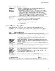
...CD-ROM drive to the audio mixer Auxiliary (AUX) Power Output Connector Provides power for the Desktop Boards D925XECV2 and D925XEBC2 Section 1.4, page 19 13 Not every manufacturing option is available in hard drive controllers (SCSI or other...control 1.3.2 Manufacturing Options Table 3 describes the manufacturing options on the Desktop Boards D925XECV2 and D925XEBC2. Product Description Table 2. Manufacturing Options Audio Subsystem Alternate (ALT) Power Input Connector Intel High Definition Audio subsystem in card connector Hardware Monitor Subsystem • Hardware ...
...CD-ROM drive to the audio mixer Auxiliary (AUX) Power Output Connector Provides power for the Desktop Boards D925XECV2 and D925XEBC2 Section 1.4, page 19 13 Not every manufacturing option is available in hard drive controllers (SCSI or other...control 1.3.2 Manufacturing Options Table 3 describes the manufacturing options on the Desktop Boards D925XECV2 and D925XEBC2. Product Description Table 2. Manufacturing Options Audio Subsystem Alternate (ALT) Power Input Connector Intel High Definition Audio subsystem in card connector Hardware Monitor Subsystem • Hardware ...
Product Specification
Page 14
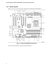
A B CD E FG H I J MM K L M LL KK JJ II N O HH P GG Q FF EE DD BB Z X CC AA Y W V U T SR Figure 1. Desktop Board D925XECV2 Components Table 4 lists the D925XECV2 components identified in Figure 1. OM16676 14 Intel Desktop Boards D925XECV2/D925XEBC2 Technical Product Specification 1.3.3 Board Layouts Figure 1 shows the location of the major components on the Desktop Board D925XECV2.
A B CD E FG H I J MM K L M LL KK JJ II N O HH P GG Q FF EE DD BB Z X CC AA Y W V U T SR Figure 1. Desktop Board D925XECV2 Components Table 4 lists the D925XECV2 components identified in Figure 1. OM16676 14 Intel Desktop Boards D925XECV2/D925XEBC2 Technical Product Specification 1.3.3 Board Layouts Figure 1 shows the location of the major components on the Desktop Board D925XECV2.

Product Specification
Page 15
Product Description Table 4. D925XECV2 Components Shown in Figure 1 Item/callout from Figure 1 A B C D E F G H I J K L M N O P Q R S T U V W X Y Z AA BB CC DD EE FF GG HH II JJ KK LL MM Description Auxiliary rear fan... bus add-in card connector Rear chassis fan connector Back panel connectors Alternate power connector +12V power connector (ATX12V) LGA775 processor socket Processor fan connector Intel 82925XE MCH DIMM Channel A sockets DIMM Channel B sockets I/O controller Power connector Diskette drive connector Parallel ATE IDE connector Battery Chassis intrusion connector BIOS Setup ...
Product Description Table 4. D925XECV2 Components Shown in Figure 1 Item/callout from Figure 1 A B C D E F G H I J K L M N O P Q R S T U V W X Y Z AA BB CC DD EE FF GG HH II JJ KK LL MM Description Auxiliary rear fan... bus add-in card connector Rear chassis fan connector Back panel connectors Alternate power connector +12V power connector (ATX12V) LGA775 processor socket Processor fan connector Intel 82925XE MCH DIMM Channel A sockets DIMM Channel B sockets I/O controller Power connector Diskette drive connector Parallel ATE IDE connector Battery Chassis intrusion connector BIOS Setup ...
Product Specification
Page 16
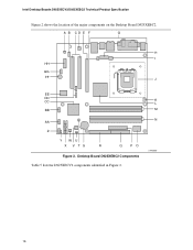
K L M N OM16686 16 Intel Desktop Boards D925XECV2/D925XEBC2 Technical Product Specification Figure 2 shows the location of the major components on the Desktop Board D925XEBC2. A B CD E F G H I HH GG FF J EE DD CC BB AA Z Y WU X V TS R Q PO Figure 2. Desktop Board D925XEBC2 Components Table 5 lists the D925XECV2 components identified in Figure 2.
K L M N OM16686 16 Intel Desktop Boards D925XECV2/D925XEBC2 Technical Product Specification Figure 2 shows the location of the major components on the Desktop Board D925XEBC2. A B CD E F G H I HH GG FF J EE DD CC BB AA Z Y WU X V TS R Q PO Figure 2. Desktop Board D925XEBC2 Components Table 5 lists the D925XECV2 components identified in Figure 2.
Product Specification
Page 18
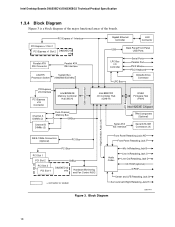
Intel Desktop Boards D925XECV2/D925XEBC2 Technical Product Specification 1.3.4 Block Diagram Figure 3 is a block diagram of the major functional areas of the boards. PCI Express x1 Interface PCI Express x1 Slot 1 PCI Express x1 Slot 2 D925XECV2 only Parallel ATA IDE Connector Parallel ATA IDE Interface ...LGA775 Processor Socket System Bus (1066/800/533 MHz) PCI Express x16 Interface PCI Express x16 Connector Intel 82925XE Memory Controller Hub (MCH) Channel A DIMMs (2) ...
Intel Desktop Boards D925XECV2/D925XEBC2 Technical Product Specification 1.3.4 Block Diagram Figure 3 is a block diagram of the major functional areas of the boards. PCI Express x1 Interface PCI Express x1 Slot 1 PCI Express x1 Slot 2 D925XECV2 only Parallel ATA IDE Connector Parallel ATA IDE Interface ...LGA775 Processor Socket System Bus (1066/800/533 MHz) PCI Express x16 Interface PCI Express x16 Connector Intel 82925XE Memory Controller Hub (MCH) Channel A DIMMs (2) ...
Product Specification
Page 19
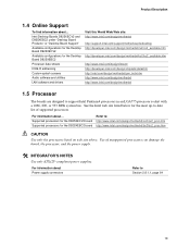
... site above. Use of supported processors. Intel Desktop Boards D925XECV2 and D925XEBC2 under "Desktop Board Products" or "Desktop Board Support" Available configurations for the Desktop Board D925XECV2 Available configurations for the D925XEBC2 board Refer to support Intel Pentium 4 processors in an LGA775 processor ...socket with a 1066, 800, or 533 MHz system bus. See the Intel web site listed below for the most...
... site above. Use of supported processors. Intel Desktop Boards D925XECV2 and D925XEBC2 under "Desktop Board Products" or "Desktop Board Support" Available configurations for the Desktop Board D925XECV2 Available configurations for the D925XEBC2 board Refer to support Intel Pentium 4 processors in an LGA775 processor ...socket with a 1066, 800, or 533 MHz system bus. See the Intel web site listed below for the most...
Product Specification
Page 20
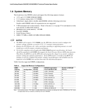
... memory to correctly configure the memory settings, but performance and reliability may not function under the determined frequency. Table 6 lists the supported DIMM configurations. Intel Desktop Boards D925XECV2/D925XEBC2 Technical Product Specification 1.6 System Memory The boards have four DIMM sockets and support the following memory features: • 1.8 V and 1.9 V DDR2 SDRAM DIMMs • 3-3-3 memory...
... memory to correctly configure the memory settings, but performance and reliability may not function under the determined frequency. Table 6 lists the supported DIMM configurations. Intel Desktop Boards D925XECV2/D925XEBC2 Technical Product Specification 1.6 System Memory The boards have four DIMM sockets and support the following memory features: • 1.8 V and 1.9 V DDR2 SDRAM DIMMs • 3-3-3 memory...
Product Specification
Page 22
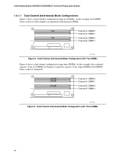
Dual Channel (Interleaved) Mode Configuration with identical DIMMs. 1 GB 1 GB Channel A, DIMM 0 Channel A, DIMM 1 Channel B, DIMM 0 Channel B, DIMM 1 OM17123 Figure 5. Intel Desktop Boards D925XECV2/D925XEBC2 Technical Product Specification 1.6.1.1 Dual Channel (Interleaved) Mode Configurations Figure 5 shows a dual channel configuration using three DIMMs. In this example, the DIMM0 (blue) sockets of Channel B. ...
Dual Channel (Interleaved) Mode Configuration with identical DIMMs. 1 GB 1 GB Channel A, DIMM 0 Channel A, DIMM 1 Channel B, DIMM 0 Channel B, DIMM 1 OM17123 Figure 5. Intel Desktop Boards D925XECV2/D925XEBC2 Technical Product Specification 1.6.1.1 Dual Channel (Interleaved) Mode Configurations Figure 5 shows a dual channel configuration using three DIMMs. In this example, the DIMM0 (blue) sockets of Channel B. ...
Product Specification
Page 24
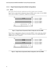
Channel B is populated. Single Channel (Asymmetric) Mode Configuration with Three DIMMs 24 Intel Desktop Boards D925XECV2/D925XEBC2 Technical Product Specification 1.6.1.2 Single Channel (Asymmetric) Mode Configurations NOTE Dual channel (Interleaved) mode configurations provide the highest memory throughput. Figure 8 shows a single channel configuration using ...
Channel B is populated. Single Channel (Asymmetric) Mode Configuration with Three DIMMs 24 Intel Desktop Boards D925XECV2/D925XEBC2 Technical Product Specification 1.6.1.2 Single Channel (Asymmetric) Mode Configurations NOTE Dual channel (Interleaved) mode configurations provide the highest memory throughput. Figure 8 shows a single channel configuration using ...

Product Specification
Page 25
...the USB connectors on the back panel The location of the front panel USB connectors on the Desktop Board D925XECV2 The location of the front panel USB connectors on the Desktop Board D925XEBC2 Refer to Figure 20, page 66 Figure 21, page 68 Figure 22, page 70 1.7.2 IDE Support The...to a USB port may not meet FCC Class B requirements, even if no device is a centralized controller for all ports. Product Description 1.7 Intel® 925XE Chipset The Intel 925XE chipset consists of the following modes: 25 The ICH6-R is attached to eight USB 2.0 ports, supports UHCI and EHCI, and uses UHCI...
...the USB connectors on the back panel The location of the front panel USB connectors on the Desktop Board D925XECV2 The location of the front panel USB connectors on the Desktop Board D925XEBC2 Refer to Figure 20, page 66 Figure 21, page 68 Figure 22, page 70 1.7.2 IDE Support The...to a USB port may not meet FCC Class B requirements, even if no device is a centralized controller for all ports. Product Description 1.7 Intel® 925XE Chipset The Intel 925XE chipset consists of the following modes: 25 The ICH6-R is attached to eight USB 2.0 ports, supports UHCI and EHCI, and uses UHCI...