Product Guide
Page 4
...576 bytes) Megabit (1,048,576 bits) Megahertz (one million hertz) Box Contents • Intel® Desktop Board • I/O shield • One ATA-66/100 cable • Four Serial ATA cables • Two Serial ATA power cables • One diskette drive cable • One rear panel USB 2.0/IEEE 1394 ...8226; Quick Reference Guide • Integration Guide • Printed Product Guide • Configuration and battery caution statement label iv Intel Desktop Board D925XCV/D925XBC Product Guide Terminology The table below gives descriptions to some common terms used in the product guide.
...576 bytes) Megabit (1,048,576 bits) Megahertz (one million hertz) Box Contents • Intel® Desktop Board • I/O shield • One ATA-66/100 cable • Four Serial ATA cables • Two Serial ATA power cables • One diskette drive cable • One rear panel USB 2.0/IEEE 1394 ...8226; Quick Reference Guide • Integration Guide • Printed Product Guide • Configuration and battery caution statement label iv Intel Desktop Board D925XCV/D925XBC Product Guide Terminology The table below gives descriptions to some common terms used in the product guide.

Product Guide
Page 6
Intel Desktop Board D925XCV/D925XBC Product Guide Installing a Processor 30 Installing the Processor Fan Heat Sink 32 Connecting the Processor Fan Heat Sink Cable 33 Removing the Processor 33 Installing ... IEEE 1394 Adapter 46 Installing the Front Panel USB/IEEE 1394/Audio Solution 47 Connecting Fans...48 Connecting Fans...48 Connecting the Auxiliary Power Output Connector (D925XCV only 49 Connecting Power Cables 50 Installing Other Connectors 52 Setting the BIOS Configuration Jumper Block 53 Clearing Passwords ...54 Back Panel Connectors ...55 Setting Up...
Intel Desktop Board D925XCV/D925XBC Product Guide Installing a Processor 30 Installing the Processor Fan Heat Sink 32 Connecting the Processor Fan Heat Sink Cable 33 Removing the Processor 33 Installing ... IEEE 1394 Adapter 46 Installing the Front Panel USB/IEEE 1394/Audio Solution 47 Connecting Fans...48 Connecting Fans...48 Connecting the Auxiliary Power Output Connector (D925XCV only 49 Connecting Power Cables 50 Installing Other Connectors 52 Setting the BIOS Configuration Jumper Block 53 Clearing Passwords ...54 Back Panel Connectors ...55 Setting Up...
Product Guide
Page 7
... of Desktop Board Mounting Holes 29 6. Location of Conformity Statement 69 Product Ecology Statements 70 EMC Regulations ...71 Product Certification Markings (Board Level 72 Figures 1. Dual Configuration Example 3 35 16. Lift the Load Plate and Don't Touch the Socket Contacts 30 8. Desktop Board D925XCV Components 11 2. Connecting the Serial ATA Cable 41 21. Connecting 2x10 Power Supply...
... of Desktop Board Mounting Holes 29 6. Location of Conformity Statement 69 Product Ecology Statements 70 EMC Regulations ...71 Product Certification Markings (Board Level 72 Figures 1. Dual Configuration Example 3 35 16. Lift the Load Plate and Don't Touch the Socket Contacts 30 8. Desktop Board D925XCV Components 11 2. Connecting the Serial ATA Cable 41 21. Connecting 2x10 Power Supply...

Product Guide
Page 10
...interface • One parallel port • One serial port • PS/2* keyboard and mouse ports Power Management • Support for Advanced Configuration and Power Interface (ACPI) • Suspend to RAM (STR) • Wake on USB, PCI, PCI ...range values Related Links For more information about Intel Desktop Board D925XCV/D925XBC, including the Technical Product Specification (TPS), BIOS updates, and device drivers, go to: http://support.intel.com/support/motherboards/desktop/ Supported Operating Systems The desktop board supports the following operating systems: • Microsoft...
...interface • One parallel port • One serial port • PS/2* keyboard and mouse ports Power Management • Support for Advanced Configuration and Power Interface (ACPI) • Suspend to RAM (STR) • Wake on USB, PCI, PCI ...range values Related Links For more information about Intel Desktop Board D925XCV/D925XBC, including the Technical Product Specification (TPS), BIOS updates, and device drivers, go to: http://support.intel.com/support/motherboards/desktop/ Supported Operating Systems The desktop board supports the following operating systems: • Microsoft...

Product Guide
Page 12
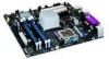
... intrusion header BIOS configuration jumper Front chassis fan header (fan speed control) Serial ATA connectors (four) Alternate power LED header Front panel header Auxiliary power output header USB 2.0 headers IEEE 1394 headers (blue) Speaker PCI bus add-in card connectors Auxiliary rear fan header (4-pin, fan speed control) 12 Intel Desktop Board D925XCV/D925XBC Product Guide Table 2.
... intrusion header BIOS configuration jumper Front chassis fan header (fan speed control) Serial ATA connectors (four) Alternate power LED header Front panel header Auxiliary power output header USB 2.0 headers IEEE 1394 headers (blue) Speaker PCI bus add-in card connectors Auxiliary rear fan header (4-pin, fan speed control) 12 Intel Desktop Board D925XCV/D925XBC Product Guide Table 2.

Product Guide
Page 14
... (four) Alternate power LED header Front panel header USB 2.0 headers IEEE 1394 headers (blue) PCI bus add-in card connectors Speaker Related Links Go to the following links for more information about: • Intel Desktop Board D925XCV/D925XBC http://www.intel.com/design/motherbd http://support.intel.com/support/motherboards/desktop • Supported processors http://support.intel.com/support/motherboards/desktop • Audio...
... (four) Alternate power LED header Front panel header USB 2.0 headers IEEE 1394 headers (blue) PCI bus add-in card connectors Speaker Related Links Go to the following links for more information about: • Intel Desktop Board D925XCV/D925XBC http://www.intel.com/design/motherbd http://support.intel.com/support/motherboards/desktop • Supported processors http://support.intel.com/support/motherboards/desktop • Audio...

Product Guide
Page 15
... Desktop Boards D925XCV and D925XBC is located on the web at: http://support.intel.com/support/motherboards/desktop/ Related Links Go to the following links or pages for more information about: • Instructions on installing or upgrading the processor, page 30 in Chapter 2 • The location of the two power connectors, page 48 in the LGA775 package. Desktop Boards D925XCV and D925XBC...
... Desktop Boards D925XCV and D925XBC is located on the web at: http://support.intel.com/support/motherboards/desktop/ Related Links Go to the following links or pages for more information about: • Instructions on installing or upgrading the processor, page 30 in Chapter 2 • The location of the two power connectors, page 48 in the LGA775 package. Desktop Boards D925XCV and D925XBC...

Product Guide
Page 16
Intel Desktop Board D925XCV/D925XBC Product Guide Main Memory NOTE To be fully compliant with all applicable Intel® SDRAM memory specifications, the desktop board should be populated with gold-plated contacts. • Support for: Unbuffered, non-registered single or double-... list of memory being available to this effect on the screen at power up. This may result in less than 4 GB of tested memory, http://support.intel.com/support/motherboards/desktop/ • SDRAM specifications, http://www.intel.com/technology/memory/pcsdram/spec/ • Installing memory, page 34 ...
Intel Desktop Board D925XCV/D925XBC Product Guide Main Memory NOTE To be fully compliant with all applicable Intel® SDRAM memory specifications, the desktop board should be populated with gold-plated contacts. • Support for: Unbuffered, non-registered single or double-... list of memory being available to this effect on the screen at power up. This may result in less than 4 GB of tested memory, http://support.intel.com/support/motherboards/desktop/ • SDRAM specifications, http://www.intel.com/technology/memory/pcsdram/spec/ • Installing memory, page 34 ...
Product Guide
Page 17
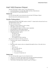
...Desktop Board D925XCV/D925XBC includes a flexible 7.1-channel audio subsystem based on an Intel high-definition audio codec: The audio subsystem features: • Impedance sensing capability for jack re-tasking • S/N (signal-to-noise) ratio: > 90 dB • Power management support for ACPI 2.0 (driver dependent) • Intel...Links Go to the following link or pages for more information about: • Audio drivers and utilities http://support.intel.com/support/motherboards/desktop/ • Installing the front panel audio solution, page 47 in Chapter 2 • The location of back panel...
...Desktop Board D925XCV/D925XBC includes a flexible 7.1-channel audio subsystem based on an Intel high-definition audio codec: The audio subsystem features: • Impedance sensing capability for jack re-tasking • S/N (signal-to-noise) ratio: > 90 dB • Power management support for ACPI 2.0 (driver dependent) • Intel...Links Go to the following link or pages for more information about: • Audio drivers and utilities http://support.intel.com/support/motherboards/desktop/ • Installing the front panel audio solution, page 47 in Chapter 2 • The location of back panel...
Product Guide
Page 18
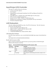
... connector with another computer on Intel's World Wide Web site at: http://support.intel.com/support/motherboards/desktop RJ-45 LAN Connector LEDs Table 5 describes the LED states when the board is powered up event interface • PCI power management support LAN Subsystem The LAN, with the Intel 82801FR, provides a Fast PCI LAN subsystem. Intel Desktop Board D925XCV/D925XBC Product Guide Input/Output...
... connector with another computer on Intel's World Wide Web site at: http://support.intel.com/support/motherboards/desktop RJ-45 LAN Connector LEDs Table 5 describes the LED states when the board is powered up event interface • PCI power management support LAN Subsystem The LAN, with the Intel 82801FR, provides a Fast PCI LAN subsystem. Intel Desktop Board D925XCV/D925XBC Product Guide Input/Output...

Product Guide
Page 20
...from a Serial ATA device, Serial ATA connector 0 is the first boot device and Serial ATA connector 3 is booted. Chassis Intrusion The desktop board supports a chassis security feature that restrict whether the BIOS Setup program can boot the computer. A supervisor password and a user password can... are then available for viewing and changing depending on page 61 for a password. Intel Desktop Board D925XCV/D925XBC Product Guide Related Links For information about the BIOS. BIOS The BIOS provides the Power-On Self-Test (POST), the BIOS Setup program, the PCI and IDE auto-configuration...
...from a Serial ATA device, Serial ATA connector 0 is the first boot device and Serial ATA connector 3 is booted. Chassis Intrusion The desktop board supports a chassis security feature that restrict whether the BIOS Setup program can boot the computer. A supervisor password and a user password can... are then available for viewing and changing depending on page 61 for a password. Intel Desktop Board D925XCV/D925XBC Product Guide Related Links For information about the BIOS. BIOS The BIOS provides the Power-On Self-Test (POST), the BIOS Setup program, the PCI and IDE auto-configuration...
Product Guide
Page 21
...control over the power management and Plug and Play functions of the fan headers. Desktop Board D925XBC has two chassis fan headers (3-pin) and one processor fan header (4-pin). Refer to Table 2 on Desktop Board D925XCV are controlled....Intel® Precision Cooling Technology) Intel Precision Cooling Technology automatically adjusts the processor fan speed based on the processor temperature and adjusts the chassis fan speeds depending on system configuration and environment. 21 The processor and chassis fan speed control features can be disabled independently through the desktop board...
...control over the power management and Plug and Play functions of the fan headers. Desktop Board D925XBC has two chassis fan headers (3-pin) and one processor fan header (4-pin). Refer to Table 2 on Desktop Board D925XCV are controlled....Intel® Precision Cooling Technology) Intel Precision Cooling Technology automatically adjusts the processor fan speed based on the processor temperature and adjusts the chassis fan speeds depending on system configuration and environment. 21 The processor and chassis fan speed control features can be disabled independently through the desktop board...
Product Guide
Page 22
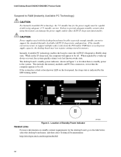
... . When signaled by the LED turning amber. The desktop board's standby power indicator, shown in Figure 3, is lit when there is indicated by a wake-up device or event, the system quickly returns to its last known awake state. Location of delivering adequate +5 V standby current. Intel Desktop Board D925XCV/D925XBC Product Guide Suspend to RAM (Instantly Available PC Technology...
... . When signaled by the LED turning amber. The desktop board's standby power indicator, shown in Figure 3, is lit when there is indicated by a wake-up device or event, the system quickly returns to its last known awake state. Location of delivering adequate +5 V standby current. Intel Desktop Board D925XCV/D925XBC Product Guide Suspend to RAM (Instantly Available PC Technology...

Product Guide
Page 26
...instructions supplied with regional laws and regulations. Ensure Electromagnetic Compatibility (EMC) Compliance Before computer integration, make sure that the power supply and other modules: • Product certifications or lack of certifications • External I/O cable shielding and filtering &#... and adhere to all warnings and cautions in the installation instructions. Intel Desktop Board D925XCV/D925XBC Product Guide Installation Precautions When you install and test the Intel desktop board, observe all of these guidelines to meet safety and regulatory requirements when installing...
...instructions supplied with regional laws and regulations. Ensure Electromagnetic Compatibility (EMC) Compliance Before computer integration, make sure that the power supply and other modules: • Product certifications or lack of certifications • External I/O cable shielding and filtering &#... and adhere to all warnings and cautions in the installation instructions. Intel Desktop Board D925XCV/D925XBC Product Guide Installation Precautions When you install and test the Intel desktop board, observe all of these guidelines to meet safety and regulatory requirements when installing...

Product Guide
Page 29
... B for instructions on installing and removing the desktop board. Desktop Board D925XBC has eight mounting holes. Figure 5. Location of the 11 mounting holes for Desktop Board D925XCV. Refer to disconnect the power before performing the procedures described here. Figure 5 shows the location of Desktop Board Mounting Holes OM16924 29 Disconnect the computer from its power source before you open the computer can...
... B for instructions on installing and removing the desktop board. Desktop Board D925XBC has eight mounting holes. Figure 5. Location of the 11 mounting holes for Desktop Board D925XCV. Refer to disconnect the power before performing the procedures described here. Figure 5 shows the location of Desktop Board Mounting Holes OM16924 29 Disconnect the computer from its power source before you open the computer can...

Product Guide
Page 30
...B A Figure 6. Intel Desktop Board D925XCV/D925XBC Product Guide Installing and Removing a Processor Instructions on how to install the processor to do so could damage the processor and the board. Installing a Processor CAUTION Before installing or removing the processor, make sure that AC power has been removed by...Figure 3 on page 25. 2. C D D Figure 7. Failure to the desktop board are given below. To install a processor, follow these instructions: 1. Lift the Load Plate and Don't Touch the Socket Contacts 30 the standby power LED should not be lit (see Figure 7, C and D).
...B A Figure 6. Intel Desktop Board D925XCV/D925XBC Product Guide Installing and Removing a Processor Instructions on how to install the processor to do so could damage the processor and the board. Installing a Processor CAUTION Before installing or removing the processor, make sure that AC power has been removed by...Figure 3 on page 25. 2. C D D Figure 7. Failure to the desktop board are given below. To install a processor, follow these instructions: 1. Lift the Load Plate and Don't Touch the Socket Contacts 30 the standby power LED should not be lit (see Figure 7, C and D).
Product Guide
Page 38
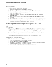
...and the card retention notch snaps into place around the RM pin. 4. Secure the card's metal bracket to reach the DIMM sockets. 9. Intel Desktop Board D925XCV/D925XBC Product Guide Removing DIMMs To remove a memory module, follow these instructions to the computer. Observe the precautions in an anti-static package. ... and/or traces may result across the PCI Express x16 connector pins. Replace the computer's cover and reconnect the AC power cord. The desktop board has an integrated PCI Express x16 card retention mechanism (RM). Installing a PCI Express x16 Card Follow these steps: 1. ...
...and the card retention notch snaps into place around the RM pin. 4. Secure the card's metal bracket to reach the DIMM sockets. 9. Intel Desktop Board D925XCV/D925XBC Product Guide Removing DIMMs To remove a memory module, follow these instructions to the computer. Observe the precautions in an anti-static package. ... and/or traces may result across the PCI Express x16 connector pins. Replace the computer's cover and reconnect the AC power cord. The desktop board has an integrated PCI Express x16 card retention mechanism (RM). Installing a PCI Express x16 Card Follow these steps: 1. ...

Product Guide
Page 42
... Option ROM user interface. 2. Exit the Option ROM user interface by pressing . Intel Desktop Board D925XCV/D925XBC Product Guide Configuring the System for Intel® Matrix Storage Technology for Serial ATA Configuring the BIOS for RAID 0), and press . 6. Go to confirm your motherboard or after the Power-On-Self-Test (POST) memory tests begin. 3. Drive Configuration; Upon re...
... Option ROM user interface. 2. Exit the Option ROM user interface by pressing . Intel Desktop Board D925XCV/D925XBC Product Guide Configuring the System for Intel® Matrix Storage Technology for Serial ATA Configuring the BIOS for RAID 0), and press . 6. Go to confirm your motherboard or after the Power-On-Self-Test (POST) memory tests begin. 3. Drive Configuration; Upon re...

Product Guide
Page 44
.... Table 6 shows the pin assignments for the headers. Table 7 shows the pin assignments for the front panel audio header. Intel Desktop Board D925XCV/D925XBC Product Guide Front Panel Audio Header Figure 21, F on page 43 shows the location of the blue IEEE 1394 headers. Table... Headers See Figure 21, E for the headers. Table 6. USB Port B Pin Signal Name 2 Power 4 D- 6 D+ 8 Ground 10 No connect 44 Table 8. USB 2.0 Header Signal Names USB Port A Pin Signal Name 1 Power 3 D- 5 D+ 7 Ground 9 Key Note: USB ports may be assigned as needed. Table ...
.... Table 6 shows the pin assignments for the headers. Table 7 shows the pin assignments for the front panel audio header. Intel Desktop Board D925XCV/D925XBC Product Guide Front Panel Audio Header Figure 21, F on page 43 shows the location of the blue IEEE 1394 headers. Table... Headers See Figure 21, E for the headers. Table 6. USB Port B Pin Signal Name 2 Power 4 D- 6 D+ 8 Ground 10 No connect 44 Table 8. USB 2.0 Header Signal Names USB Port A Pin Signal Name 1 Power 3 D- 5 D+ 7 Ground 9 Key Note: USB ports may be assigned as needed. Table ...

Product Guide
Page 49
... Advanced ! Installing and Replacing Desktop Board Components Connecting the Auxiliary Power Output Connector (D925XCV only) Figure 25 shows the location of this connector. Auxiliary Power Output Connector The D925XCV board includes a male 1x4 power connector that limit the current draw to provide power for storage devices. 49 If a power supply with a 24-pin (2x12) main power cable. The 1x4 connector is...
... Advanced ! Installing and Replacing Desktop Board Components Connecting the Auxiliary Power Output Connector (D925XCV only) Figure 25 shows the location of this connector. Auxiliary Power Output Connector The D925XCV board includes a male 1x4 power connector that limit the current draw to provide power for storage devices. 49 If a power supply with a 24-pin (2x12) main power cable. The 1x4 connector is...

