
Product Guide
Page 5
Contents 1 Desktop Board Features Manufacturing Options ...11 Supported Operating Systems 11 Desktop Board Components 12 Processor ...16 Main Memory ...17 Intel® 915P Express Chipset 18 Audio Subsystem ...18 Input/Output (I/O) Controller 19 LAN Subsystem (Optional 19 LAN Subsystem Software 20 RJ-45 LAN Connector LEDs 20 Hi-Speed USB 2.0 Support 20 Enhanced IDE Interface ...20 Serial ATA...
Contents 1 Desktop Board Features Manufacturing Options ...11 Supported Operating Systems 11 Desktop Board Components 12 Processor ...16 Main Memory ...17 Intel® 915P Express Chipset 18 Audio Subsystem ...18 Input/Output (I/O) Controller 19 LAN Subsystem (Optional 19 LAN Subsystem Software 20 RJ-45 LAN Connector LEDs 20 Hi-Speed USB 2.0 Support 20 Enhanced IDE Interface ...20 Serial ATA...

Product Guide
Page 9
... Wide Web site at: http://support.intel.com/support/motherboards/desktop/ Intel® 915P Express Chipset consisting of: • Intel® 82915P Memory Controller Hub (MCH) with Direct Media Interface • Intel® 82801FB I/O Controller Hub (ICH6) • Firmware Hub (FWH) • Intel 915P Express Chipset • Intel® High Definition Audio • Realtek codec Desktop boards D915PGN and D915PCY: • Four PCI...
... Wide Web site at: http://support.intel.com/support/motherboards/desktop/ Intel® 915P Express Chipset consisting of: • Intel® 82915P Memory Controller Hub (MCH) with Direct Media Interface • Intel® 82801FB I/O Controller Hub (ICH6) • Firmware Hub (FWH) • Intel 915P Express Chipset • Intel® High Definition Audio • Realtek codec Desktop boards D915PGN and D915PCY: • Four PCI...

Product Guide
Page 10
... processor temperature and chassis fan speeds based on system temperature • Voltage sensing to detect out of range values Related Links For more information about Intel Desktop Board D915PGN/D915PSY/D915PCY/D915PCM, including the Technical Product Specification (TPS), BIOS updates, and device drivers, go to: http://support.intel.com/support/motherboards/desktop/ 10 Intel Desktop Board D915PGN/D915PSY/D915PCY/D915PCM Product Guide Table 1.
... processor temperature and chassis fan speeds based on system temperature • Voltage sensing to detect out of range values Related Links For more information about Intel Desktop Board D915PGN/D915PSY/D915PCY/D915PCM, including the Technical Product Specification (TPS), BIOS updates, and device drivers, go to: http://support.intel.com/support/motherboards/desktop/ 10 Intel Desktop Board D915PGN/D915PSY/D915PCY/D915PCM Product Guide Table 1.

Product Guide
Page 11
Table 2. Option LAN Manufacturing Option Description Intel® 82562EZ 10/100 Mbit/sec Platform LAN Connect (PLC) device with RJ-45 connector Supported Operating Systems The desktop board supports the following operating systems: • Microsoft Windows* 2000 • Microsoft Windows XP 11 Desktop Board Features Manufacturing Options Table 2 shows the manufacturing option for Desktop Board D915PGN/D915PSY/ D915PCY/D915PCM.
Table 2. Option LAN Manufacturing Option Description Intel® 82562EZ 10/100 Mbit/sec Platform LAN Connect (PLC) device with RJ-45 connector Supported Operating Systems The desktop board supports the following operating systems: • Microsoft Windows* 2000 • Microsoft Windows XP 11 Desktop Board Features Manufacturing Options Table 2 shows the manufacturing option for Desktop Board D915PGN/D915PSY/ D915PCY/D915PCM.

Product Guide
Page 15
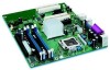
...B C D E F G H I J K L M N O P Q R S T U Desktop Boards D915PSY and D915PCM Components Description Front panel audio header PCI Express x16 connector Rear chassis fan header (fan speed ... to the following links for more information about: • Intel Desktop Board D915PGN/D915PSY/ D915PCY/D915PCM http://www.intel.com/design/motherbd http://support.intel.com/support/motherboards/desktop • Supported processors http://support.intel.com/support/motherboards/desktop • Audio software and utilities http://www.intel.com/design/motherbd • LAN software and drivers http://www...
...B C D E F G H I J K L M N O P Q R S T U Desktop Boards D915PSY and D915PCM Components Description Front panel audio header PCI Express x16 connector Rear chassis fan header (fan speed ... to the following links for more information about: • Intel Desktop Board D915PGN/D915PSY/ D915PCY/D915PCM http://www.intel.com/design/motherbd http://support.intel.com/support/motherboards/desktop • Supported processors http://support.intel.com/support/motherboards/desktop • Audio software and utilities http://www.intel.com/design/motherbd • LAN software and drivers http://www...

Product Guide
Page 16
The processor connects to the Intel desktop board through the LGA775 socket. The supported processors list for Desktop Boards D915PGN, D915PSY, D915PCY, and D915PCM is located on the web at: http://support.intel.com/support/motherboards/desktop/ Related Links Go to the following links or pages for more information about: • Supported Intel® processors for Desktop Board D915PGN/D915PSY/D915PCY/D915PCM http://support.intel.com/support/motherboards/desktop/ • Instructions on installing...
The processor connects to the Intel desktop board through the LGA775 socket. The supported processors list for Desktop Boards D915PGN, D915PSY, D915PCY, and D915PCM is located on the web at: http://support.intel.com/support/motherboards/desktop/ Related Links Go to the following links or pages for more information about: • Supported Intel® processors for Desktop Board D915PGN/D915PSY/D915PCY/D915PCM http://support.intel.com/support/motherboards/desktop/ • Instructions on installing...

Product Guide
Page 17
... Main Memory NOTE To be fully compliant with all applicable Intel® SDRAM memory specifications, the board should be populated with gold-plated contacts. • Support for normal operation. The BIOS will see a notification to this effect on the screen at power up. Desktop Board D915PGN/D915PSY Memory Configurations Memory Speed DDR 400 Processor Pentium 4 processor...
... Main Memory NOTE To be fully compliant with all applicable Intel® SDRAM memory specifications, the board should be populated with gold-plated contacts. • Support for normal operation. The BIOS will see a notification to this effect on the screen at power up. Desktop Board D915PGN/D915PSY Memory Configurations Memory Speed DDR 400 Processor Pentium 4 processor...
Product Guide
Page 18
... of tested memory, http://support.intel.com/support/motherboards/desktop/ • SDRAM specifications, http://www.intel.com/technology/memory/pcsdram/spec/ • Installing memory, page 36 in less than 4 GB of the following devices: • Intel 82915P Memory Controller Hub (MCH) • Intel 82801FB I /O Controller Hub (ICH6) • Realtek ALC860 audio codec 18 Intel Desktop Board D915PGN/D915PSY/D915PCY/D915PCM Product Guide...
... of tested memory, http://support.intel.com/support/motherboards/desktop/ • SDRAM specifications, http://www.intel.com/technology/memory/pcsdram/spec/ • Installing memory, page 36 in less than 4 GB of the following devices: • Intel 82915P Memory Controller Hub (MCH) • Intel 82801FB I /O Controller Hub (ICH6) • Realtek ALC860 audio codec 18 Intel Desktop Board D915PGN/D915PSY/D915PCY/D915PCM Product Guide...

Product Guide
Page 19
Desktop Board Features • Microphone input that supports: Microphone array Acoustic Echo (AEC) Beam Forming (BF) Noise Supression (NX) technology The subsystem includes the following connectors: • Front panel audio connector, including pins ... Mic in or Center LFE out Related Links Go to the following link or pages for more information about: • Audio drivers and utilities http://support.intel.com/support/motherboards/desktop/ • Installing the front panel audio solution, page 45 in Chapter 2 • The location of audio connectors, page Figure 22 on page 47 Input...
Desktop Board Features • Microphone input that supports: Microphone array Acoustic Echo (AEC) Beam Forming (BF) Noise Supression (NX) technology The subsystem includes the following connectors: • Front panel audio connector, including pins ... Mic in or Center LFE out Related Links Go to the following link or pages for more information about: • Audio drivers and utilities http://support.intel.com/support/motherboards/desktop/ • Installing the front panel audio solution, page 45 in Chapter 2 • The location of audio connectors, page Figure 22 on page 47 Input...

Product Guide
Page 20
...USB 1.1 devices will function normally at : http://support.intel.com/support/motherboards/desktop RJ-45 LAN Connector LEDs Two LEDs are backward compatible with another computer on Intel's World Wide Web site at USB 1.1 speeds. USB 2.0 support requires both an operating system and drivers that ...support USB 2.0. Disabling Hi-Speed USB in the BIOS reverts all USB 2.0 ports to accommodate operating systems that have an unshielded cable attached to a USB port might not meet FCC Class B requirements, even if no device or a low-speed USB device is established. Intel Desktop Board D915PGN...
...USB 1.1 devices will function normally at : http://support.intel.com/support/motherboards/desktop RJ-45 LAN Connector LEDs Two LEDs are backward compatible with another computer on Intel's World Wide Web site at USB 1.1 speeds. USB 2.0 support requires both an operating system and drivers that ...support USB 2.0. Disabling Hi-Speed USB in the BIOS reverts all USB 2.0 ports to accommodate operating systems that have an unshielded cable attached to a USB port might not meet FCC Class B requirements, even if no device or a low-speed USB device is established. Intel Desktop Board D915PGN...

Product Guide
Page 21
...BIOS Setup program. Expandability The desktop boards support the following the instructions on page 59 in Chapter 3. You can be updated by specifying manual configuration in the Firmware Hub. The BIOS can override the auto-configuration options by following : • Desktop boards D915PGN and D915PCY: One PCI ...Express x16 add-in card Two PCI Express x1 add-in cards Four PCI add-in cards • Desktop boards D915PSY and D915PCM: One PCI Express x16 add-in card One...
...BIOS Setup program. Expandability The desktop boards support the following the instructions on page 59 in Chapter 3. You can be updated by specifying manual configuration in the Firmware Hub. The BIOS can override the auto-configuration options by following : • Desktop boards D915PGN and D915PCY: One PCI ...Express x16 add-in card Two PCI Express x1 add-in cards Four PCI add-in cards • Desktop boards D915PSY and D915PCM: One PCI Express x16 add-in card One...
Product Guide
Page 22
...booted. Setup options are set for the BIOS Setup and for booting the computer, with the desktop board requires an operating system that provides full ACPI support. The security feature uses a mechanical switch on the chassis that can be connected to the ... chassis intrusion header. Chassis Intrusion The board supports a chassis security feature that detects if the chassis cover has been removed. The use of the power connectors. 22 Power Connectors The desktop board has three power connectors. Intel Desktop Board D915PGN/D915PSY/D915PCY/D915PCM Product Guide Security Passwords...
...booted. Setup options are set for the BIOS Setup and for booting the computer, with the desktop board requires an operating system that provides full ACPI support. The security feature uses a mechanical switch on the chassis that can be connected to the ... chassis intrusion header. Chassis Intrusion The board supports a chassis security feature that detects if the chassis cover has been removed. The use of the power connectors. 22 Power Connectors The desktop board has three power connectors. Intel Desktop Board D915PGN/D915PSY/D915PCY/D915PCM Product Guide Security Passwords...
Product Guide
Page 24
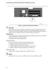
... events from USB. 24 Location of a USB peripheral that supports Wake from the PCI and/or USB buses exceeds power supply capacity, the desktop board may lose register settings stored in memory. If the standby current necessary to support the standard Instantly Available (ACPI S3 sleep state) configuration. Intel Desktop Board D915PGN/D915PSY/D915PCY/D915PCM Product Guide Figure 3.
... events from USB. 24 Location of a USB peripheral that supports Wake from the PCI and/or USB buses exceeds power supply capacity, the desktop board may lose register settings stored in memory. If the standby current necessary to support the standard Instantly Available (ACPI S3 sleep state) configuration. Intel Desktop Board D915PGN/D915PSY/D915PCY/D915PCM Product Guide Figure 3.

Product Guide
Page 25
...and 100-year calendar. The battery on the desktop board. Speaker A speaker is asserted, the computer wakes from an ACPI S1 or S3 state. The speaker provides audible error code (beep code) information during the Power-On Self-Test (POST). PME# Wakeup Support When the PME# signal on the PCI bus... is mounted on the desktop board keeps the clock current when the computer is turned off . 25 See Chapter 2 starting on page 27 for ...
...and 100-year calendar. The battery on the desktop board. Speaker A speaker is asserted, the computer wakes from an ACPI S1 or S3 state. The speaker provides audible error code (beep code) information during the Power-On Self-Test (POST). PME# Wakeup Support When the PME# signal on the PCI bus... is mounted on the desktop board keeps the clock current when the computer is turned off . 25 See Chapter 2 starting on page 27 for ...

Product Guide
Page 28
... modules, contact the supplier's technical support to find out how you can ensure that instruct you to refer computer servicing to wires that could be careful of the newly completed computer. 28 Intel Desktop Board D915PGN/D915PSY/D915PCY/D915PCM Product Guide Installation Precautions... When you install and test the Intel desktop board, observe all warnings and cautions that your computer meets safety and regulatory ...
... modules, contact the supplier's technical support to find out how you can ensure that instruct you to refer computer servicing to wires that could be careful of the newly completed computer. 28 Intel Desktop Board D915PGN/D915PSY/D915PCY/D915PCM Product Guide Installation Precautions... When you install and test the Intel desktop board, observe all warnings and cautions that your computer meets safety and regulatory ...
Product Guide
Page 34
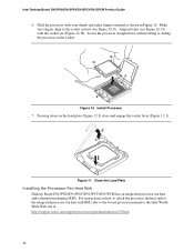
... the Load Plate Installing the Processor Fan Heat Sink Desktop Board D915PGN/D915PSY/D915PCY/D915PCM has an integrated processor fan heat sink retention mechanism (RM). Make sure fingers align to the boxed processor manual or the Intel World Wide Web site at: http://support.intel.com/support/processors/pentium4/intnotes478.htm 34 II Pressing down without tilting...
... the Load Plate Installing the Processor Fan Heat Sink Desktop Board D915PGN/D915PSY/D915PCY/D915PCM has an integrated processor fan heat sink retention mechanism (RM). Make sure fingers align to the boxed processor manual or the Intel World Wide Web site at: http://support.intel.com/support/processors/pentium4/intnotes478.htm 34 II Pressing down without tilting...

Product Guide
Page 35
... to remove the processor fan heat sink and processor, refer to the processor installation manual or the Intel World Wide Web site at: http://support.intel.com/support/processors/pentium4/intnotes478.htm 35 Installing and Replacing Desktop Board Components Connecting the Processor Fan Heat Sink Cable Connect the processor fan heat sink cable to the Processor...
... to remove the processor fan heat sink and processor, refer to the processor installation manual or the Intel World Wide Web site at: http://support.intel.com/support/processors/pentium4/intnotes478.htm 35 Installing and Replacing Desktop Board Components Connecting the Processor Fan Heat Sink Cable Connect the processor fan heat sink cable to the Processor...

Product Guide
Page 36
... socket locations. Dual Configuration Example 1 36 You can access the PC Serial Presence Detect Specification at: http://www.intel.com/technology/memory/pcsdram/spec/ Desktop boards D915PGN and D915PCY have four 240-pin DDR2 DIMM sockets arranged as DIMM 0 (blue) and DIMM 1 (black) ... 13) in both Channel A and Channel B. Intel Desktop Board D915PGN/D915PSY/D915PCY/D915PCM Product Guide Installing and Removing Memory NOTE To be fully compliant with all applicable Intel® SDRAM memory specifications, the boards require DIMMs that support the Serial Presence Detect (SPD) data structure....
... socket locations. Dual Configuration Example 1 36 You can access the PC Serial Presence Detect Specification at: http://www.intel.com/technology/memory/pcsdram/spec/ Desktop boards D915PGN and D915PCY have four 240-pin DDR2 DIMM sockets arranged as DIMM 0 (blue) and DIMM 1 (black) ... 13) in both Channel A and Channel B. Intel Desktop Board D915PGN/D915PSY/D915PCY/D915PCM Product Guide Installing and Removing Memory NOTE To be fully compliant with all applicable Intel® SDRAM memory specifications, the boards require DIMMs that support the Serial Presence Detect (SPD) data structure....

Product Guide
Page 42
... Do not connect an ATA device as a slave on page 27. • Attach the cable end with the single connector to the Intel desktop board (Figure 19, A). • Attach the cable end with drives using slower IDE transfer protocols. For example, do not connect an ATA hard drive...; Observe the precautions in "Before You Begin" on the same IDE cable as a slave to the drives (Figure 19, B). The cable supports the ATA-66/100 transfer protocol. Intel Desktop Board D915PGN/D915PSY/D915PCY/D915PCM Product Guide Connecting the IDE Cable The IDE cable can connect two drives to that of the slowest drive...
... Do not connect an ATA device as a slave on page 27. • Attach the cable end with the single connector to the Intel desktop board (Figure 19, A). • Attach the cable end with drives using slower IDE transfer protocols. For example, do not connect an ATA hard drive...; Observe the precautions in "Before You Begin" on the same IDE cable as a slave to the drives (Figure 19, B). The cable supports the ATA-66/100 transfer protocol. Intel Desktop Board D915PGN/D915PSY/D915PCY/D915PCM Product Guide Connecting the IDE Cable The IDE cable can connect two drives to that of the slowest drive...

Product Guide
Page 43
Either end of the cable can be connected to the connector (Figure 20, A) on the board. 3. Attach either cable end to the SATA drive or the connector on page 27. 2. A B Figure 20. Installing and Replacing Desktop Board Components Connecting the Serial ATA Cable The SATA cable (4-conductor) supports the Serial ATA protocol and connects a single drive to the drive (Figure 20, B). Connecting the Serial ATA Cable OM16884 43 For correct cable function: 1. Observe the precaution in "Before You Begin" on the board. Attach the other cable end to the desktop board.
Either end of the cable can be connected to the connector (Figure 20, A) on the board. 3. Attach either cable end to the SATA drive or the connector on page 27. 2. A B Figure 20. Installing and Replacing Desktop Board Components Connecting the Serial ATA Cable The SATA cable (4-conductor) supports the Serial ATA protocol and connects a single drive to the drive (Figure 20, B). Connecting the Serial ATA Cable OM16884 43 For correct cable function: 1. Observe the precaution in "Before You Begin" on the board. Attach the other cable end to the desktop board.


