
Product Guide
Page 5
... Manufacturing Options ...11 Supported Operating Systems 11 Desktop Board Components 12 Processor ...16 Main Memory ...17 Intel® 915P Express Chipset 18 Audio Subsystem ...18 Input/Output (I/O) Controller 19 LAN Subsystem (Optional 19 LAN Subsystem Software 20 RJ-45 LAN Connector LEDs 20 Hi-Speed USB 2.0 Support 20 ...
... Manufacturing Options ...11 Supported Operating Systems 11 Desktop Board Components 12 Processor ...16 Main Memory ...17 Intel® 915P Express Chipset 18 Audio Subsystem ...18 Input/Output (I/O) Controller 19 LAN Subsystem (Optional 19 LAN Subsystem Software 20 RJ-45 LAN Connector LEDs 20 Hi-Speed USB 2.0 Support 20 ...

Product Guide
Page 6
Intel Desktop Board D915PGN/D915PSY/D915PCY/D915PCM Product Guide Installing the I/O Shield ...30 Installing and Removing the Desktop Board 31 Installing and Removing a Processor 32 Installing a Processor 32 Installing the Processor Fan Heat Sink 34 Connecting the Processor Fan Heat ... 42 Connecting the Serial ATA Cable 43 Connecting Internal Headers 44 Installing a Front Panel Audio Solution 45 Connecting USB 2.0 Headers 46 Connecting the Front Panel Header 46 Setting Up the Flexible 6-Channel Audio with Jack Re-tasking 47 Connecting Fan and Power Cables 48 Connecting Fan Cables 48...
Intel Desktop Board D915PGN/D915PSY/D915PCY/D915PCM Product Guide Installing the I/O Shield ...30 Installing and Removing the Desktop Board 31 Installing and Removing a Processor 32 Installing a Processor 32 Installing the Processor Fan Heat Sink 34 Connecting the Processor Fan Heat ... 42 Connecting the Serial ATA Cable 43 Connecting Internal Headers 44 Installing a Front Panel Audio Solution 45 Connecting USB 2.0 Headers 46 Connecting the Front Panel Header 46 Setting Up the Flexible 6-Channel Audio with Jack Re-tasking 47 Connecting Fan and Power Cables 48 Connecting Fan Cables 48...

Product Guide
Page 7
... 4. Remove the Protective Cover 33 9. Remove the Processor from the Protective Cover 33 10. Back Panel Audio Connectors for Desktop Boards D915PGN and D915PCY 51 27. Desktop Boards D915PSY and D915PCM Components 15 5. Front Panel Audio Header Signal Names 45 vii Intel Desktop Boards D915PSY and D915PCM Components 14 3. Location of Conformity Statement 69 Product Ecology Statements 70 EMC Regulations...
... 4. Remove the Protective Cover 33 9. Remove the Processor from the Protective Cover 33 10. Back Panel Audio Connectors for Desktop Boards D915PGN and D915PCY 51 27. Desktop Boards D915PSY and D915PCM Components 15 5. Front Panel Audio Header Signal Names 45 vii Intel Desktop Boards D915PSY and D915PCM Components 14 3. Location of Conformity Statement 69 Product Ecology Statements 70 EMC Regulations...

Product Guide
Page 9
... of : • Intel® 82915P Memory Controller Hub (MCH) with Direct Media Interface • Intel® 82801FB I/O Controller Hub (ICH6) • Firmware Hub (FWH) • Intel 915P Express Chipset • Intel® High Definition Audio • Realtek codec Desktop boards D915PGN and D915PCY: •... to support up to 4 GB of Intel® Desktop Board D915PGN/D915PSY/ D915PCY/D915PCM. Table 1. For the latest list of tested memory, refer to the Intel World Wide Web site at: http://support.intel.com/support/motherboards/desktop/ Intel® 915P Express Chipset consisting of memory...
... of : • Intel® 82915P Memory Controller Hub (MCH) with Direct Media Interface • Intel® 82801FB I/O Controller Hub (ICH6) • Firmware Hub (FWH) • Intel 915P Express Chipset • Intel® High Definition Audio • Realtek codec Desktop boards D915PGN and D915PCY: •... to support up to 4 GB of Intel® Desktop Board D915PGN/D915PSY/ D915PCY/D915PCM. Table 1. For the latest list of tested memory, refer to the Intel World Wide Web site at: http://support.intel.com/support/motherboards/desktop/ Intel® 915P Express Chipset consisting of memory...

Product Guide
Page 13
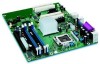
Label A B C D E F G H I J K L M N O P Q R S T U V Desktop Boards D915PGN and D915PCY Components Description PCI Express x1 connectors Front panel audio header PCI Express x16 connector Rear chassis fan header 1 (fan speed control) Alternate power connector (1x4) 12 V processor core voltage connector (2x2) Processor socket Processor ...) Serial ATA connectors Power LED header Front panel header USB 2.0 headers Speaker PCI bus add-in card connectors Rear chassis fan header 2 (always on) 13 Desktop Board Features Table 3.
Label A B C D E F G H I J K L M N O P Q R S T U V Desktop Boards D915PGN and D915PCY Components Description PCI Express x1 connectors Front panel audio header PCI Express x16 connector Rear chassis fan header 1 (fan speed control) Alternate power connector (1x4) 12 V processor core voltage connector (2x2) Processor socket Processor ...) Serial ATA connectors Power LED header Front panel header USB 2.0 headers Speaker PCI bus add-in card connectors Rear chassis fan header 2 (always on) 13 Desktop Board Features Table 3.

Product Guide
Page 15
... Express x1 connector Related Links Go to the following links for more information about: • Intel Desktop Board D915PGN/D915PSY/ D915PCY/D915PCM http://www.intel.com/design/motherbd http://support.intel.com/support/motherboards/desktop • Supported processors http://support.intel.com/support/motherboards/desktop • Audio software and utilities http://www.intel.com/design/motherbd • LAN software and drivers http://www...
... Express x1 connector Related Links Go to the following links for more information about: • Intel Desktop Board D915PGN/D915PSY/ D915PCY/D915PCM http://www.intel.com/design/motherbd http://support.intel.com/support/motherboards/desktop • Supported processors http://support.intel.com/support/motherboards/desktop • Audio software and utilities http://www.intel.com/design/motherbd • LAN software and drivers http://www...
Product Guide
Page 18
...about the Intel 915P chipset: http://developer.intel.com/design/nav/pcserver.htm Audio Subsystem Desktop Board D915PGN/D915PSY/D915PCY/D915PCM includes a flexible 6-channel audio subsystem based on a Realtek Semiconductor Corporation codec: The audio subsystem ...intel.com/support/motherboards/desktop/ • SDRAM specifications, http://www.intel.com/technology/memory/pcsdram/spec/ • Installing memory, page 36 in Chapter 2 Intel® 915P Express Chipset The Intel 915P Express Chipset consists of the following devices: • Intel 82915P Memory Controller Hub (MCH) • Intel...
...about the Intel 915P chipset: http://developer.intel.com/design/nav/pcserver.htm Audio Subsystem Desktop Board D915PGN/D915PSY/D915PCY/D915PCM includes a flexible 6-channel audio subsystem based on a Realtek Semiconductor Corporation codec: The audio subsystem ...intel.com/support/motherboards/desktop/ • SDRAM specifications, http://www.intel.com/technology/memory/pcsdram/spec/ • Installing memory, page 36 in Chapter 2 Intel® 915P Express Chipset The Intel 915P Express Chipset consists of the following devices: • Intel 82915P Memory Controller Hub (MCH) • Intel...

Product Guide
Page 19
Desktop Board Features • Microphone input that supports: Microphone array Acoustic Echo (AEC) Beam Forming (BF) Noise Supression (NX) technology The subsystem includes the following connectors: • Front panel audio connector, including pins for: Line out Line in • Back panel audio connectors that are configurable through the drivers of the audio...information about: • Audio drivers and utilities http://support.intel.com/support/motherboards/desktop/ • Installing the front panel audio solution, page 45 in Chapter 2 • The location of audio connectors, page Figure ...
Desktop Board Features • Microphone input that supports: Microphone array Acoustic Echo (AEC) Beam Forming (BF) Noise Supression (NX) technology The subsystem includes the following connectors: • Front panel audio connector, including pins for: Line out Line in • Back panel audio connectors that are configurable through the drivers of the audio...information about: • Audio drivers and utilities http://support.intel.com/support/motherboards/desktop/ • Installing the front panel audio solution, page 45 in Chapter 2 • The location of audio connectors, page Figure ...

Product Guide
Page 27
...open the computer or perform any of the computer chassis. 27 2 Installing and Replacing Desktop Board Components This chapter tells you how to: • Install the I/O shield • Install and remove the desktop board • Install and remove a processor and memory • Install and remove a ...x16 PCI Express card • Connect the IDE and Serial ATA cables • Connect the front panel header • Install the front panel audio and USB solutions •...
...open the computer or perform any of the computer chassis. 27 2 Installing and Replacing Desktop Board Components This chapter tells you how to: • Install the I/O shield • Install and remove the desktop board • Install and remove a processor and memory • Install and remove a ...x16 PCI Express card • Connect the IDE and Serial ATA cables • Connect the front panel header • Install the front panel audio and USB solutions •...

Product Guide
Page 44
Intel Desktop Board D915PGN/D915PSY/D915PCY/D915PCM Product Guide Connecting Internal Headers Before connecting cables to the internal headers, observe the precautions in "Before You Begin" on page 27. ...) USB B 1 2 Power (+5V) 3 4 D5 6 D+ 7 8 Ground 10 N/C D 9 No Connection On/Off 87 65 Reset Power LED 43 HD LED 3 21 1 C B Item A B C D E Description Chassis intrusion Power LED audio Front panel USB 2.0 Front panel...
Intel Desktop Board D915PGN/D915PSY/D915PCY/D915PCM Product Guide Connecting Internal Headers Before connecting cables to the internal headers, observe the precautions in "Before You Begin" on page 27. ...) USB B 1 2 Power (+5V) 3 4 D5 6 D+ 7 8 Ground 10 N/C D 9 No Connection On/Off 87 65 Reset Power LED 43 HD LED 3 21 1 C B Item A B C D E Description Chassis intrusion Power LED audio Front panel USB 2.0 Front panel...

Product Guide
Page 45
... the computer and disconnect the AC power cord. 3. Replace the cover. Installing and Replacing Desktop Board Components Installing a Front Panel Audio Solution Figure 21, E on page 27. 2. Locate the yellow front panel audio header. 5. Connect the audio cable to the front panel audio header, follow these steps: 1. Turn off all peripheral devices connected to the computer...
... the computer and disconnect the AC power cord. 3. Replace the cover. Installing and Replacing Desktop Board Components Installing a Front Panel Audio Solution Figure 21, E on page 27. 2. Locate the yellow front panel audio header. 5. Connect the audio cable to the front panel audio header, follow these steps: 1. Turn off all peripheral devices connected to the computer...

Product Guide
Page 47
...Replacing Desktop Board Components Setting Up the Flexible 6-Channel Audio with Jack Re-tasking After installing the Realtek audio driver from the Intel® Express Installer CD-ROM, the multichannel audio feature can be enabled. and 6-channel audio configurations. Back Panel Audio Connectors for both 4- For 6-channel audio, ...C Item A B C OM15694 Description Rear left/right out or Line In Front left /right out (A) for Flexible 6-Channel Audio System Multi-Channel Analog Audio Connect two speakers to the front left/right out (B) and two speakers to the center LFE out (C). 47
...Replacing Desktop Board Components Setting Up the Flexible 6-Channel Audio with Jack Re-tasking After installing the Realtek audio driver from the Intel® Express Installer CD-ROM, the multichannel audio feature can be enabled. and 6-channel audio configurations. Back Panel Audio Connectors for both 4- For 6-channel audio, ...C Item A B C OM15694 Description Rear left/right out or Line In Front left /right out (A) for Flexible 6-Channel Audio System Multi-Channel Analog Audio Connect two speakers to the front left/right out (B) and two speakers to the center LFE out (C). 47

Product Guide
Page 54
Intel Desktop Board D915PGN/D915PSY/D915PCY/D915PCM Product Guide Back Panel Connectors NOTE The line out connector, located on the back panel, is designed to this output. Line In RJ45 Figure 28. Back Panel Connectors OM16887 54 Figure 28 shows the location of the back panel connectors. Poor audio quality may occur if passive (non-amplified) speakers are connected to power either headphones or amplified speakers only.
Intel Desktop Board D915PGN/D915PSY/D915PCY/D915PCM Product Guide Back Panel Connectors NOTE The line out connector, located on the back panel, is designed to this output. Line In RJ45 Figure 28. Back Panel Connectors OM16887 54 Figure 28 shows the location of the back panel connectors. Poor audio quality may occur if passive (non-amplified) speakers are connected to power either headphones or amplified speakers only.


