
D915PDT Technical Product Specification
Page 8
Intel Desktop Board D915PDT Technical Product Specification 18. Chassis Fan Connectors 50 22. DC Loading Characteristics 59 30. Safety Regulations ...65 34. EMC Regulations ...70 36. Runtime Code Uncompressed .... Boot Device Menu Options 77 40. Bus Initialization Checkpoints 87 46. BIOS Setup Program Menu Bar 74 38. Upper Nibble High Byte Functions 87 47. Main Power Connector 51 23. Product Certification Markings 72 37. Lower Nibble High Byte Functions 88 48. Serial ATA Connectors 50 20. Processor Fan Connector 50...
Intel Desktop Board D915PDT Technical Product Specification 18. Chassis Fan Connectors 50 22. DC Loading Characteristics 59 30. Safety Regulations ...65 34. EMC Regulations ...70 36. Runtime Code Uncompressed .... Boot Device Menu Options 77 40. Bus Initialization Checkpoints 87 46. BIOS Setup Program Menu Bar 74 38. Upper Nibble High Byte Functions 87 47. Main Power Connector 51 23. Product Certification Markings 72 37. Lower Nibble High Byte Functions 88 48. Serial ATA Connectors 50 20. Processor Fan Connector 50...

D915PDT Technical Product Specification
Page 37
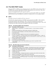
... wake capabilities • Instantly Available PC technology • Resume on the wake devices supported and manufacturing options. For information about The location of the main power connector The signal names of standby current required depends on Ring • Wake from USB • Wake from PS/2 keyboard • PME#... CAUTION Ensure that provides full ACPI support. 1.11.2.1 Power Connector ATX12V-compliant power supplies can turn off ). The total amount of the main power connector Refer to the power state it is in the BIOS Setup program's Boot menu. The method used .
... wake capabilities • Instantly Available PC technology • Resume on the wake devices supported and manufacturing options. For information about The location of the main power connector The signal names of standby current required depends on Ring • Wake from USB • Wake from PS/2 keyboard • PME#... CAUTION Ensure that provides full ACPI support. 1.11.2.1 Power Connector ATX12V-compliant power supplies can turn off ). The total amount of the main power connector Refer to the power state it is in the BIOS Setup program's Boot menu. The method used .

D915PDT Technical Product Specification
Page 51
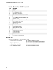
... with either 2 x 10 or 2 x 12 main power cables. Main Power Connector Pin Signal Name 1 +3.3 V 2 +3.3 V 3 Ground 4 +5 V 5 Ground 6 +5 V 7 Ground 8 PWRGD (Power Good) 9 +5 V (Standby) 10 +12 V 11 +12 V (Note) 12 2 x 12 connector detect (Note) Pin Signal Name 13 +3.3 V 14 -12 V 15 Ground 16 PS-ON# (power supply remote on Intel desktop boards. This connector provides power...
... with either 2 x 10 or 2 x 12 main power cables. Main Power Connector Pin Signal Name 1 +3.3 V 2 +3.3 V 3 Ground 4 +5 V 5 Ground 6 +5 V 7 Ground 8 PWRGD (Power Good) 9 +5 V (Standby) 10 +12 V 11 +12 V (Note) 12 2 x 12 connector detect (Note) Pin Signal Name 13 +3.3 V 14 -12 V 15 Ground 16 PS-ON# (power supply remote on Intel desktop boards. This connector provides power...

D915PDT Technical Product Specification
Page 73
...Legacy USB Support...75 3.6 BIOS Updates ...76 3.7 Boot Options ...77 3.8 Adjusting Boot Speed 78 3.9 BIOS Security Features 79 3.1 Introduction The board uses an Intel® BIOS that is stored in configure mode. The initial production BIOSs are identified as DT91510J.86A. The BIOS Setup program can be used to.... When the BIOS Setup configuration jumper is set to put the Desktop Board in the BIOS and reports if the two match. Maintenance Main Advanced Security Power Boot Exit NOTE The maintenance menu is displayed only when the Desktop Board is in the Firmware Hub (FWH) and...
...Legacy USB Support...75 3.6 BIOS Updates ...76 3.7 Boot Options ...77 3.8 Adjusting Boot Speed 78 3.9 BIOS Security Features 79 3.1 Introduction The board uses an Intel® BIOS that is stored in configure mode. The initial production BIOSs are identified as DT91510J.86A. The BIOS Setup program can be used to.... When the BIOS Setup configuration jumper is set to put the Desktop Board in the BIOS and reports if the two match. Maintenance Main Advanced Security Power Boot Exit NOTE The maintenance menu is displayed only when the Desktop Board is in the Firmware Hub (FWH) and...

D915PDT Technical Product Specification
Page 74
... program, the BIOS automatically sets up the PCI IDE connector with independent I /O space, and other system resources. Intel Desktop Board D915PDT Technical Product Specification Table 37 lists the BIOS Setup program menu features. PCI devices may be available for the current ...the function keys available for Logical Block Addressing (LBA) and 74 Table 37. BIOS Setup Program Menu Bar Maintenance Main Advanced Security Clears passwords and displays processor information Displays processor and memory configuration Configures advanced features available through the chipset ...
... program, the BIOS automatically sets up the PCI IDE connector with independent I /O space, and other system resources. Intel Desktop Board D915PDT Technical Product Specification Table 37 lists the BIOS Setup program menu features. PCI devices may be available for the current ...the function keys available for Logical Block Addressing (LBA) and 74 Table 37. BIOS Setup Program Menu Bar Maintenance Main Advanced Security Clears passwords and displays processor information Displays processor and memory configuration Configures advanced features available through the chipset ...

D915PDT Technical Product Specification
Page 75
You can override the autoconfiguration options by the BIOS allowing you apply power to install an operating system that supports USB. The main component of SMBIOS is the Management Information Format (MIF) database, which contains information about the computing system and its components. The MIF database defines the ...
You can override the autoconfiguration options by the BIOS allowing you apply power to install an operating system that supports USB. The main component of SMBIOS is the Management Information Format (MIF) database, which contains information about the computing system and its components. The MIF database defines the ...
D915PDT Technical Product Specification
Page 83
...Shadow RAM and give control to boot from floppy and ATAPI device failed. Init code Checksum verification starting. If either it is recovery mode or main BIOS checksum is successful, give control to check point E9). 83 Table 42 defines the uncompressed INIT code checkpoints, Table 43 describes the boot ... image to F000 shadow RAM and give control to check point D7 for ATAPI (LS-120, Zip) devices. E8 Initialize extra (Intel Recovery) Module. Give two beeps. This code is Disabled. The POST card can decode the port and display the contents on a medium such as a ...
...Shadow RAM and give control to boot from floppy and ATAPI device failed. Init code Checksum verification starting. If either it is recovery mode or main BIOS checksum is successful, give control to check point E9). 83 Table 42 defines the uncompressed INIT code checkpoints, Table 43 describes the boot ... image to F000 shadow RAM and give control to check point D7 for ATAPI (LS-120, Zip) devices. E8 Initialize extra (Intel Recovery) Module. Give two beeps. This code is Disabled. The POST card can decode the port and display the contents on a medium such as a ...

English Product Guide
Page 5
Contents 1 Desktop Board Features Supported Operating Systems 10 45H Desktop Board Components 11 46H Processor...13 47H Main Memory ...14 48H Intel® 915P Express Chipset 15 49H Audio Subsystem ...15 50H Input/Output (I/O) Controller 16 51H LAN Subsystem ...16 52H LAN Subsystem Software 16 ...19 62H Chassis Intrusion...19 63H Power Management Features 19 64H ACPI...19 65H Power Connectors...19 6H Fan Connectors...20 67H Fan Speed Control (Intel® Precision Cooling Technology 20 68H Suspend to RAM (Instantly Available PC Technology 20 69H Resume on Ring...21 70H Wake from USB...21...
Contents 1 Desktop Board Features Supported Operating Systems 10 45H Desktop Board Components 11 46H Processor...13 47H Main Memory ...14 48H Intel® 915P Express Chipset 15 49H Audio Subsystem ...15 50H Input/Output (I/O) Controller 16 51H LAN Subsystem ...16 52H LAN Subsystem Software 16 ...19 62H Chassis Intrusion...19 63H Power Management Features 19 64H ACPI...19 65H Power Connectors...19 6H Fan Connectors...20 67H Fan Speed Control (Intel® Precision Cooling Technology 20 68H Suspend to RAM (Instantly Available PC Technology 20 69H Resume on Ring...21 70H Wake from USB...21...

English Product Guide
Page 9
...Main Memory 6H Chipset 7H Audio 8H Expansion 9H Capabilities Peripheral 10H Interfaces LAN 1H microATX (9.60" x 9.60") Support for: • Intel® Pentium® 4 processor in the LGA775 package • Intel...Intel® 915P Express Chipset consisting of the desktop board. Table ...Intel® 82915P Memory Controller Hub (MCH) with Direct Media Interface • Intel® 82801FB I/O Controller Hub (ICH6) • 8-Mbit Firmware Hub (FWH) • Intel 915P Express Chipset • Intel... • PS/2* keyboard and mouse ports Integrated Intel® GD82562GX 10/100 Mbit/sec Platform LAN Connect ...
...Main Memory 6H Chipset 7H Audio 8H Expansion 9H Capabilities Peripheral 10H Interfaces LAN 1H microATX (9.60" x 9.60") Support for: • Intel® Pentium® 4 processor in the LGA775 package • Intel...Intel® 915P Express Chipset consisting of the desktop board. Table ...Intel® 82915P Memory Controller Hub (MCH) with Direct Media Interface • Intel® 82801FB I/O Controller Hub (ICH6) • 8-Mbit Firmware Hub (FWH) • Intel 915P Express Chipset • Intel... • PS/2* keyboard and mouse ports Integrated Intel® GD82562GX 10/100 Mbit/sec Platform LAN Connect ...
English Product Guide
Page 12
... S T U Desktop Board D915PDT Components Description Speaker PCI Express x1 connector Front panel audio header PCI Express x16 connector Rear chassis fan header (fan speed control) Back panel I/O connectors 12 V processor core voltage connector (2x2) Processor socket Processor fan header (4-pin, fan speed control) Main power connector (2x12) Diskette drive...: Go to the following links for more information about: • Intel Desktop Board D915PDT http://www.intel.com/design/motherbd 16H http://support.intel.com/support/motherboards/desktop 17H • Supported processors • Audio ...
... S T U Desktop Board D915PDT Components Description Speaker PCI Express x1 connector Front panel audio header PCI Express x16 connector Rear chassis fan header (fan speed control) Back panel I/O connectors 12 V processor core voltage connector (2x2) Processor socket Processor fan header (4-pin, fan speed control) Main power connector (2x12) Diskette drive...: Go to the following links for more information about: • Intel Desktop Board D915PDT http://www.intel.com/design/motherbd 16H http://support.intel.com/support/motherboards/desktop 17H • Supported processors • Audio ...
English Product Guide
Page 14
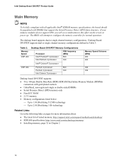
... Detect (SPD) data structure. The BIOS will see a notification to the following links or pages for normal operation. Intel Desktop Board D915PDT Product Guide Main Memory NOTE To be fully compliant with all applicable Intel® SDRAM memory specifications, the board should be populated with gold-plated contacts • Unbuffered, non-registered single or...
... Detect (SPD) data structure. The BIOS will see a notification to the following links or pages for normal operation. Intel Desktop Board D915PDT Product Guide Main Memory NOTE To be fully compliant with all applicable Intel® SDRAM memory specifications, the board should be populated with gold-plated contacts • Unbuffered, non-registered single or...

English Product Guide
Page 43
... page 23. 247H 248H 2. Connect the 12 V processor core voltage power supply cable to the 2x12 connector. 43 Connecting Power Supply Cables OM18060 1. Connect the main power supply cable to the 2x2 connector. 3. Observe the precautions in damage to the desktop board and/or power supply. Figure 21 shows the location...
... page 23. 247H 248H 2. Connect the 12 V processor core voltage power supply cable to the 2x12 connector. 43 Connecting Power Supply Cables OM18060 1. Connect the main power supply cable to the 2x2 connector. 3. Observe the precautions in damage to the desktop board and/or power supply. Figure 21 shows the location...