
User Manual
Page 5
Contents 1 Desktop Board Features Manufacturing Options ...11 Supported Operating Systems 11 Desktop Board Components 12 Processor ...16 Main Memory ...17 Intel® 915G Express Chipset 18 Graphics Subsystem ...19 Audio Subsystem ...19 Input/Output (I/O) Controller 20 LAN Subsystem (Optional)...... 23 Security Passwords...23 Chassis Intrusion...23 Power Management Features 23 ACPI...23 Power Connectors...24 Fan Connectors...24 Fan Speed Control (Intel® Precision Cooling Technology 24 Suspend to RAM (Instantly Available PC Technology 24 Resume on Ring ...25 Wake from USB ...26...
Contents 1 Desktop Board Features Manufacturing Options ...11 Supported Operating Systems 11 Desktop Board Components 12 Processor ...16 Main Memory ...17 Intel® 915G Express Chipset 18 Graphics Subsystem ...19 Audio Subsystem ...19 Input/Output (I/O) Controller 20 LAN Subsystem (Optional)...... 23 Security Passwords...23 Chassis Intrusion...23 Power Management Features 23 ACPI...23 Power Connectors...24 Fan Connectors...24 Fan Speed Control (Intel® Precision Cooling Technology 24 Suspend to RAM (Instantly Available PC Technology 24 Resume on Ring ...25 Wake from USB ...26...
User Manual
Page 6
Intel Desktop Board D915GEV/D915GUX/D915GAV/D915GAG Product Guide Installing and Removing the Desktop Board 31 Installing and Removing a Processor 32 Installing a Processor 32 Installing the Processor Fan Heat Sink 34 Connecting the Processor Fan Heat Sink Cable 35 Removing the Processor 35 Installing and Removing Memory...53 Back Panel Connectors...54 Replacing the Battery...55 3 BIOS Updating the BIOS with the Intel® Express BIOS Update Utility 59 Updating the BIOS with the Iflash Memory Update Utility 60 Obtaining the BIOS Update File 60 Updating the BIOS ...60 Recovering the ...
Intel Desktop Board D915GEV/D915GUX/D915GAV/D915GAG Product Guide Installing and Removing the Desktop Board 31 Installing and Removing a Processor 32 Installing a Processor 32 Installing the Processor Fan Heat Sink 34 Connecting the Processor Fan Heat Sink Cable 35 Removing the Processor 35 Installing and Removing Memory...53 Back Panel Connectors...54 Replacing the Battery...55 3 BIOS Updating the BIOS with the Intel® Express BIOS Update Utility 59 Updating the BIOS with the Iflash Memory Update Utility 60 Obtaining the BIOS Update File 60 Updating the BIOS ...60 Recovering the ...
User Manual
Page 7
... and PCI Express Add-in Card, and Peripheral Interface Connectors for Flexible 6-Channel Audio System 47 24. Installing the I/O Shield 30 6. Contents 5 Desktop Board Resources Memory Map ...71 DMA Channels ...71 Interrupts ...72 A Error Messages and Indicators BIOS Beep Codes...73 BIOS Error Messages ...74 B Regulatory Compliance Safety Regulations ...77 European...
... and PCI Express Add-in Card, and Peripheral Interface Connectors for Flexible 6-Channel Audio System 47 24. Installing the I/O Shield 30 6. Contents 5 Desktop Board Resources Memory Map ...71 DMA Channels ...71 Interrupts ...72 A Error Messages and Indicators BIOS Beep Codes...73 BIOS Error Messages ...74 B Regulatory Compliance Safety Regulations ...77 European...
User Manual
Page 8
......9 2. Front Panel Audio Header Signal Names 45 10. System Memory Map...71 14. DMA Channels ...71 15. Manufacturing Options 11 3. BIOS Error Messages...74 18. Safety Regulations ...77 19. Intel Desktop Board D915GEV/D915GUX/D915GAV/D915GAG Product Guide Tables 1. Desktop Boards D915GAG and D915GUX Components 15 5. Front Panel Header Signal Names 46 12. Desktop...
......9 2. Front Panel Audio Header Signal Names 45 10. System Memory Map...71 14. DMA Channels ...71 15. Manufacturing Options 11 3. BIOS Error Messages...74 18. Safety Regulations ...77 19. Intel Desktop Board D915GEV/D915GUX/D915GAV/D915GAG Product Guide Tables 1. Desktop Boards D915GAG and D915GUX Components 15 5. Front Panel Header Signal Names 46 12. Desktop...
User Manual
Page 9
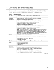
... less than 4 GB of the desktop board. Table 1 summarizes the major features of memory being available to the operating system and applications. Table 1. This may result in card connectors (SMBus routed to 4 GB of Intel® Desktop Board D915GEV/D915GUX/ D915GAV/D915GAG. 1 Desktop Board Features This chapter briefly describes the main features of...
... less than 4 GB of the desktop board. Table 1 summarizes the major features of memory being available to the operating system and applications. Table 1. This may result in card connectors (SMBus routed to 4 GB of Intel® Desktop Board D915GEV/D915GUX/ D915GAV/D915GAG. 1 Desktop Board Features This chapter briefly describes the main features of...
User Manual
Page 10
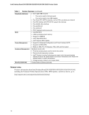
... • One serial port • PS/2* keyboard and mouse ports BIOS • Intel/AMI BIOS • 4 Mbit symmetrical flash memory • Support for SMBIOS • Intel® Rapid BIOS Boot • Intel® Express BIOS Update Power Management • Support for Advanced Configuration and Power Interface ...out of range values Security (Optional) Trusted Platform Module (Optional) Related Links: For more information about Intel Desktop Board D915GEV/D915GUX/D915GAV/D915GAG, including the Technical Product Specification (TPS), BIOS updates, and device drivers, go to: http://support...
... • One serial port • PS/2* keyboard and mouse ports BIOS • Intel/AMI BIOS • 4 Mbit symmetrical flash memory • Support for SMBIOS • Intel® Rapid BIOS Boot • Intel® Express BIOS Update Power Management • Support for Advanced Configuration and Power Interface ...out of range values Security (Optional) Trusted Platform Module (Optional) Related Links: For more information about Intel Desktop Board D915GEV/D915GUX/D915GAV/D915GAG, including the Technical Product Specification (TPS), BIOS updates, and device drivers, go to: http://support...
User Manual
Page 17
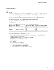
... will attempt to this effect on the screen at power up. Desktop Board Features Main Memory NOTE To be fully compliant with all applicable Intel® SDRAM memory specifications, the board should be populated with gold-plated contacts • Unbuffered, non-registered... single or double-sided DIMMs • Serial Presence Detect (SPD) memory only • Non-ECC RAM • 2.5 V memory • Memory configuration listed below: ...
... will attempt to this effect on the screen at power up. Desktop Board Features Main Memory NOTE To be fully compliant with all applicable Intel® SDRAM memory specifications, the board should be populated with gold-plated contacts • Unbuffered, non-registered... single or double-sided DIMMs • Serial Presence Detect (SPD) memory only • Non-ECC RAM • 2.5 V memory • Memory configuration listed below: ...
User Manual
Page 18
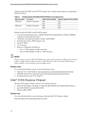
...pages for more information about the Intel 915G Express Chipset: http://developer.intel.com/design/nav/pcserver.htm 18 Table 6. This may result in Table 6. Desktop Board D915GEV/D915GUX Memory Configurations Memory Speed Processor FSB frequency (MHz) Memory Speed Outcome (MHz) DDR2 533...Firmware Hub (FWH) Related Link: Go to the operating system and applications. Intel Desktop Board D915GEV/D915GUX/D915GAV/D915GAG Product Guide Desktop boards D915GEV and D915GUX support dual or single channel memory configurations defined in less than 4 GB of the following link for more ...
...pages for more information about the Intel 915G Express Chipset: http://developer.intel.com/design/nav/pcserver.htm 18 Table 6. This may result in Table 6. Desktop Board D915GEV/D915GUX Memory Configurations Memory Speed Processor FSB frequency (MHz) Memory Speed Outcome (MHz) DDR2 533...Firmware Hub (FWH) Related Link: Go to the operating system and applications. Intel Desktop Board D915GEV/D915GUX/D915GAV/D915GAG Product Guide Desktop boards D915GEV and D915GUX support dual or single channel memory configurations defined in less than 4 GB of the following link for more ...
User Manual
Page 24
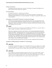
...the fan headers. Failure to identify controlled chassis fan headers. Desktop boards D915GAG and D915GUX have a 4-pin processor fan header. System fan noise may lose register settings stored in memory. 24 The processor and chassis fan speed control features can damage the power supply ...and/or effect ACPI S3 sleep state functionality. Intel Desktop Board D915GEV/D915GUX/D915GAV/D915GAG Product Guide Power Connectors The desktop boards ...
...the fan headers. Failure to identify controlled chassis fan headers. Desktop boards D915GAG and D915GUX have a 4-pin processor fan header. System fan noise may lose register settings stored in memory. 24 The processor and chassis fan speed control features can damage the power supply ...and/or effect ACPI S3 sleep state functionality. Intel Desktop Board D915GEV/D915GUX/D915GAV/D915GAG Product Guide Power Connectors The desktop boards ...
User Manual
Page 25
...off . The desktop board's standby power indicator, shown in the S3 sleep state, the computer will appear to the system. This includes the memory modules and PCI bus connectors, even when the computer appears to its last known awake state. Desktop Board Features Instantly Available PC technology enables ... has a dual-colored power LED on Ring can be summarized as follows: • Resumes operation from the left-hand menu: http://support.intel.com/support/motherboards/desktop/ Resume on Ring The operation of Resume on the front panel, the sleep state is standby power to be unmasked for...
...off . The desktop board's standby power indicator, shown in the S3 sleep state, the computer will appear to the system. This includes the memory modules and PCI bus connectors, even when the computer appears to its last known awake state. Desktop Board Features Instantly Available PC technology enables ... has a dual-colored power LED on Ring can be summarized as follows: • Resumes operation from the left-hand menu: http://support.intel.com/support/motherboards/desktop/ Resume on Ring The operation of Resume on the front panel, the sleep state is standby power to be unmasked for...
User Manual
Page 27
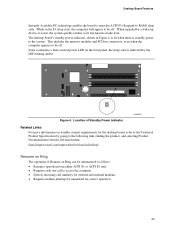
.... Some circuitry on the board can continue to : • Install the I/O shield • Install and remove the desktop board • Install and remove a processor and memory • Install and remove a PCI Express x16 card • Connect the IDE and Serial ATA cables • Connect internal headers • Set up a log to...
.... Some circuitry on the board can continue to : • Install the I/O shield • Install and remove the desktop board • Install and remove a processor and memory • Install and remove a PCI Express x16 card • Connect the IDE and Serial ATA cables • Connect internal headers • Set up a log to...

User Manual
Page 36
...) in both channels A and B (see Figure 14). 1 GB, 400 MHz 1 GB, 400 MHz Channel A Channel B Figure 14. Intel Desktop Board D915GEV/D915GUX/D915GAV/D915GAG Product Guide Installing and Removing Memory NOTE To be fully compliant with all applicable Intel SDRAM memory specifications, the boards require DIMMs that support the Serial Presence Detect (SPD) data structure.
...) in both channels A and B (see Figure 14). 1 GB, 400 MHz 1 GB, 400 MHz Channel A Channel B Figure 14. Intel Desktop Board D915GEV/D915GUX/D915GAV/D915GAG Product Guide Installing and Removing Memory NOTE To be fully compliant with all applicable Intel SDRAM memory specifications, the boards require DIMMs that support the Serial Presence Detect (SPD) data structure.

User Manual
Page 37
... will result in DIMM 0 (blue) and DIMM 1 (black) of channel A. Installing and Replacing Desktop Board Components If additional memory is to be used, install another matched pair of DIMMs in DIMM 1 (black) in either DIMM 0 or DIMM 1 of channel B (see Figure 15). 256 MB, ...
... will result in DIMM 0 (blue) and DIMM 1 (black) of channel A. Installing and Replacing Desktop Board Components If additional memory is to be used, install another matched pair of DIMMs in DIMM 1 (black) in either DIMM 0 or DIMM 1 of channel B (see Figure 15). 256 MB, ...

User Manual
Page 38
To make sure you have the correct DIMM, place the DIMM on the illustration in the DIMM sockets prior to installing the PCI Express video card to avoid interference with the memory retention mechanism. DDR DDR2 mm 1 2 3 4 5 6 7 8 9 10 11 12 13 OM16847 Figure 17. Matching the Correct DIMM 38 Intel Desktop Board D915GEV/D915GUX/D915GAV/D915GAG Product Guide Installing DIMMs CAUTION Install memory in Figure 17.
To make sure you have the correct DIMM, place the DIMM on the illustration in the DIMM sockets prior to installing the PCI Express video card to avoid interference with the memory retention mechanism. DDR DDR2 mm 1 2 3 4 5 6 7 8 9 10 11 12 13 OM16847 Figure 17. Matching the Correct DIMM 38 Intel Desktop Board D915GEV/D915GUX/D915GAV/D915GAG Product Guide Installing DIMMs CAUTION Install memory in Figure 17.
User Manual
Page 55
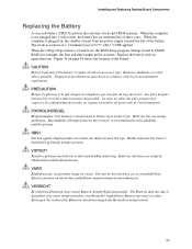
...övårdsbestämmelserna. Installing and Replacing Desktop Board Components Replacing the Battery A coin-cell battery (CR2032) powers the real-time clock and CMOS memory. VARO Räjähdysvaara, jos pariston tyyppi on hävitettävä paikallisten ympäristömääräysten mukaisesti. Figure 30 on...
...övårdsbestämmelserna. Installing and Replacing Desktop Board Components Replacing the Battery A coin-cell battery (CR2032) powers the real-time clock and CMOS memory. VARO Räjähdysvaara, jos pariston tyyppi on hävitettävä paikallisten ympäristömääräysten mukaisesti. Figure 30 on...

User Manual
Page 59
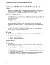
...your hard drive where it was saved. Follow the instructions provided in an automated update utility that combines the functionality of the Intel® Flash Memory Update Utility and the ease-of use of Windows-based installation wizards. To update the BIOS with the... the BIOS settings for multiple identical systems.) 4. Go to the D915GEV/D915GUX/D915GAV/D915GAG page, click "[view] Latest BIOS updates," and select the Express BIOS Update utility file. 3. Close all other applications. Updating the BIOS with the Intel Express BIOS Update utility: 1. Your system will be used to a ...
...your hard drive where it was saved. Follow the instructions provided in an automated update utility that combines the functionality of the Intel® Flash Memory Update Utility and the ease-of use of Windows-based installation wizards. To update the BIOS with the... the BIOS settings for multiple identical systems.) 4. Go to the D915GEV/D915GUX/D915GAV/D915GAG page, click "[view] Latest BIOS updates," and select the Express BIOS Update utility file. 3. Close all other applications. Updating the BIOS with the Intel Express BIOS Update utility: 1. Your system will be used to a ...
User Manual
Page 60
... computer with the BIOS update diskette in flash memory • Update the language section of the BIOS by navigating to the Desktop Board D915GEV/D915GUX/D915GAV/D915GAG page on the Intel World Wide Web site at: http://support.intel.com/support/motherboards/desktop Navigate to view the...Web provides a simple method for creating a bootable flash memory update floppy that contains all the files you to reboot the system. 3. Intel Desktop Board D915GEV/D915GUX/D915GAV/D915GAG Product Guide Updating the BIOS with the Iflash Memory Update Utility With the Iflash BIOS update utility you to...
... computer with the BIOS update diskette in flash memory • Update the language section of the BIOS by navigating to the Desktop Board D915GEV/D915GUX/D915GAV/D915GAG page on the Intel World Wide Web site at: http://support.intel.com/support/motherboards/desktop Navigate to view the...Web provides a simple method for creating a bootable flash memory update floppy that contains all the files you to reboot the system. 3. Intel Desktop Board D915GEV/D915GUX/D915GAV/D915GAG Product Guide Updating the BIOS with the Iflash Memory Update Utility With the Iflash BIOS update utility you to...

User Manual
Page 71
... (for ECP or EPP) DMA controller Open Open Open 71 EFFFF 800 K - 896 K C8000 - DFFFF 640 K - 800 K 639 K - 640 K A0000 - System Memory Map Address Range (decimal) Address Range (hex) 1024 K - 4194304 K 100000 - C7FFF 9FC00 - 9FFFF 512 K - 639 K 0 K - 512 K 80000 - 9FBFF ... KB 160 KB 1 KB 127 KB 512 KB Description Extended Memory Runtime BIOS Reserved Available high DOS memory (open to the PCI bus) Video memory and BIOS Extended BIOS data (movable by memory manager software) Extended conventional memory Conventional memory DMA Channels Table 14. FFFFF 896 K - 960 K E0000...
... (for ECP or EPP) DMA controller Open Open Open 71 EFFFF 800 K - 896 K C8000 - DFFFF 640 K - 800 K 639 K - 640 K A0000 - System Memory Map Address Range (decimal) Address Range (hex) 1024 K - 4194304 K 100000 - C7FFF 9FC00 - 9FFFF 512 K - 639 K 0 K - 512 K 80000 - 9FBFF ... KB 160 KB 1 KB 127 KB 512 KB Description Extended Memory Runtime BIOS Reserved Available high DOS memory (open to the PCI bus) Video memory and BIOS Extended BIOS data (movable by memory manager software) Extended conventional memory Conventional memory DMA Channels Table 14. FFFFF 896 K - 960 K E0000...
User Manual
Page 73
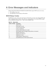
... found) 73 Beep Codes Number of Beeps 1 2 3 4 5 6 7 8 9 10 11 Description Refresh failure Parity cannot be toggled (memory failure or not present) Exception interrupt error Display memory R/W error (Reserved; A Error Messages and Indicators Desktop Board D915GEV/D915GUX/D915GAV/D915GAG reports POST errors in two ways: • By sounding a beep code • By displaying an...
... found) 73 Beep Codes Number of Beeps 1 2 3 4 5 6 7 8 9 10 11 Description Refresh failure Parity cannot be toggled (memory failure or not present) Exception interrupt error Display memory R/W error (Reserved; A Error Messages and Indicators Desktop Board D915GEV/D915GUX/D915GAV/D915GAG reports POST errors in two ways: • By sounding a beep code • By displaying an...
User Manual
Page 74
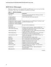
...be unlocked to continue to access diskette drive controller. Make sure keyboard is valid. Intel Desktop Board D915GEV/D915GUX/D915GAV/D915GAG Product Guide BIOS Error Messages When a recoverable error occurs during the memory test. Replace the battery soon. Run Setup to set correct values. DMA Error Error...Not Set The time and/or date values stored in the keyboard connection. CMOS Checksum Bad The CMOS checksum is correct. CMOS memory may be updated. Run Setup to reset values. NVRAM was unable to protected mode during the POST, the BIOS displays an ...
...be unlocked to continue to access diskette drive controller. Make sure keyboard is valid. Intel Desktop Board D915GEV/D915GUX/D915GAV/D915GAG Product Guide BIOS Error Messages When a recoverable error occurs during the memory test. Replace the battery soon. Run Setup to set correct values. DMA Error Error...Not Set The time and/or date values stored in the keyboard connection. CMOS Checksum Bad The CMOS checksum is correct. CMOS memory may be updated. Run Setup to reset values. NVRAM was unable to protected mode during the POST, the BIOS displays an ...


