
Product Guide
Page 3
Contents 1 Desktop Board Features Board Components ...9 Processor ...11 Main Memory ...12 Intel® 850 Chipset ...12 Intel® 82850 Memory Controller Hub (MCH 12 Intel® 82801BA I/O Controller Hub (ICH2 13 Firmware Hub (FWH 13 Input/Output (I/O) Controller 13 ...BIOS ...15 PCI Auto Configuration 15 IDE Auto Configuration 16 Security Passwords 16 LAN Subsystem (Optional 17 LAN Subsystem Software 17 RJ-45 LAN Connector LEDs 17 Speaker...17 Battery...17 Power Management Features 18 Instantly Available Technology 18 Resume on Ring...20 2 Installing and Replacing Desktop Board...
Contents 1 Desktop Board Features Board Components ...9 Processor ...11 Main Memory ...12 Intel® 850 Chipset ...12 Intel® 82850 Memory Controller Hub (MCH 12 Intel® 82801BA I/O Controller Hub (ICH2 13 Firmware Hub (FWH 13 Input/Output (I/O) Controller 13 ...BIOS ...15 PCI Auto Configuration 15 IDE Auto Configuration 16 Security Passwords 16 LAN Subsystem (Optional 17 LAN Subsystem Software 17 RJ-45 LAN Connector LEDs 17 Speaker...17 Battery...17 Power Management Features 18 Instantly Available Technology 18 Resume on Ring...20 2 Installing and Replacing Desktop Board...

Product Guide
Page 4
Intel Desktop Boards D850MD and D850MV Product Guide Installing and Removing an AGP Card Retention Mechanism and Card 32 Installing the AGP Card Retention Mechanism 32 Installing an AGP Card 34 Removing the AGP Card from the Retention Mechanism 34 Removing the AGP Card Retention Mechanism 35 Connecting the IDE Cable 36 Setting the BIOS... 3 Updating the BIOS Updating the BIOS with the Intel® Express BIOS Update Utility 43 Updating the BIOS with the Intel® Flash Memory Update Utility 43 Obtaining the BIOS Update File 43 Updating the BIOS...44 Recovering the BIOS 44 4 Using the...
Intel Desktop Boards D850MD and D850MV Product Guide Installing and Removing an AGP Card Retention Mechanism and Card 32 Installing the AGP Card Retention Mechanism 32 Installing an AGP Card 34 Removing the AGP Card from the Retention Mechanism 34 Removing the AGP Card Retention Mechanism 35 Connecting the IDE Cable 36 Setting the BIOS... 3 Updating the BIOS Updating the BIOS with the Intel® Express BIOS Update Utility 43 Updating the BIOS with the Intel® Flash Memory Update Utility 43 Obtaining the BIOS Update File 43 Updating the BIOS...44 Recovering the BIOS 44 4 Using the...

Product Guide
Page 5
... Applications 85 Figures 1. Location of the BIOS Configuration Jumper 37 20. Connecting the Processor Fan Cable to the Board 26 9. AGP Card with a Retention ... 66 22. D850MV Board Power and Hardware Control Connectors 69 25. D850MD Board Add-in Card and Peripheral Interface Connectors 70 v D850MD Board Components 9 2. D850MV Board Components 10 3. D850MV Board Mounting Screw Holes...Memory Module 31 14. Contents Desktop Board Resources 73 Memory Map ...73 DMA Channels ...73 I /O Shield 22 5. Location of Standby Power Indicator 19 4. D850MD Board Mounting Screw Holes 23 6. ...
... Applications 85 Figures 1. Location of the BIOS Configuration Jumper 37 20. Connecting the Processor Fan Cable to the Board 26 9. AGP Card with a Retention ... 66 22. D850MV Board Power and Hardware Control Connectors 69 25. D850MD Board Add-in Card and Peripheral Interface Connectors 70 v D850MD Board Components 9 2. D850MV Board Components 10 3. D850MV Board Mounting Screw Holes...Memory Module 31 14. Contents Desktop Board Resources 73 Memory Map ...73 DMA Channels ...73 I /O Shield 22 5. Location of Standby Power Indicator 19 4. D850MD Board Mounting Screw Holes 23 6. ...

Product Guide
Page 6
Intel Desktop Boards D850MD and D850MV Product Guide 26. Standby Current Requirements 20 5. Advanced Menu ...51 12. PCI Configuration Submenu 52 13. Security Menu...60 21. Exit Menu...64 27. I/O Map...74 30. Safety Regulations...81 34. ACPI Submenu ...62 24. Interrupts ...76 31. D850MV Board... Add-in Card and Peripheral Interface Connectors 71 27. Processors Supported by the Desktop Board 11 3. RJ-45 LAN Connector LEDs 17 4. Jumper Settings for the BIOS Setup Program Modes (J9H2 37 6. Primary/Secondary...
Intel Desktop Boards D850MD and D850MV Product Guide 26. Standby Current Requirements 20 5. Advanced Menu ...51 12. PCI Configuration Submenu 52 13. Security Menu...60 21. Exit Menu...64 27. I/O Map...74 30. Safety Regulations...81 34. ACPI Submenu ...62 24. Interrupts ...76 31. D850MV Board... Add-in Card and Peripheral Interface Connectors 71 27. Processors Supported by the Desktop Board 11 3. RJ-45 LAN Connector LEDs 17 4. Jumper Settings for the BIOS Setup Program Modes (J9H2 37 6. Primary/Secondary...

Product Guide
Page 8
Feature Summary (continued) BIOS • Intel/AMI BIOS • 4 Mbit symmetrical flash memory • Support for SMBIOS Power Management • Support for Advanced Configuration and Power Interface (ACPI...• SCSI hard drive activity LED connector for the front panel • Speaker ✏ NOTE For information about Intel® desktop boards, including technical product specifications, BIOS updates, and device drivers, go to the Intel World Wide Web site at: http://support.intel.com/support/motherboards/desktop 8 Intel Desktop Boards D850MD and D850MV Product Guide Table 1.
Feature Summary (continued) BIOS • Intel/AMI BIOS • 4 Mbit symmetrical flash memory • Support for SMBIOS Power Management • Support for Advanced Configuration and Power Interface (ACPI...• SCSI hard drive activity LED connector for the front panel • Speaker ✏ NOTE For information about Intel® desktop boards, including technical product specifications, BIOS updates, and device drivers, go to the Intel World Wide Web site at: http://support.intel.com/support/motherboards/desktop 8 Intel Desktop Boards D850MD and D850MV Product Guide Table 1.

Product Guide
Page 9
...) (tachometer input) X BIOS configuration jumper J Intel 82850 Memory Controller Hub (MCH) Y SCSI hard drive activity LED connector K Processor socket Z Intel 82801BA I/O Controller Hub (ICH2) L RIMM sockets AA PCI bus add-in card connectors M RIMM fan connector (fan 1) BB Communication and Networking Riser (CNR) N Power connector (optional) O Floppy drive connector Figure 1. Desktop Board Features Board Components Figure...
...) (tachometer input) X BIOS configuration jumper J Intel 82850 Memory Controller Hub (MCH) Y SCSI hard drive activity LED connector K Processor socket Z Intel 82801BA I/O Controller Hub (ICH2) L RIMM sockets AA PCI bus add-in card connectors M RIMM fan connector (fan 1) BB Communication and Networking Riser (CNR) N Power connector (optional) O Floppy drive connector Figure 1. Desktop Board Features Board Components Figure...

Product Guide
Page 10
Intel Desktop Boards D850MD and D850MV Product Guide Figure 2 shows the location of the major components on the D850MV board. A B CD E F G CC H I BB J AA K L Z Y X M W V TR US P Q O N OM12073 A ADI AD1885 audio codec P Primary IDE connector B ... processor core voltage connector W Speaker I Processor fan connector (CPU fan) (tachometer input) X BIOS configuration jumper J Intel 82850 Memory Controller Hub (MCH) Y SCSI hard drive activity LED connector K Processor socket Z Intel 82801BA I/O Controller Hub (ICH2) L RIMM sockets AA PCI bus add-in card connectors M...
Intel Desktop Boards D850MD and D850MV Product Guide Figure 2 shows the location of the major components on the D850MV board. A B CD E F G CC H I BB J AA K L Z Y X M W V TR US P Q O N OM12073 A ADI AD1885 audio codec P Primary IDE connector B ... processor core voltage connector W Speaker I Processor fan connector (CPU fan) (tachometer input) X BIOS configuration jumper J Intel 82850 Memory Controller Hub (MCH) Y SCSI hard drive activity LED connector K Processor socket Z Intel 82801BA I/O Controller Hub (ICH2) L RIMM sockets AA PCI bus add-in card connectors M...

Product Guide
Page 13
... the clock current when the computer is turned off. 13 Desktop Board Features Intel® 82801BA I/O Controller Hub (ICH2) The ICH2 has these features: • Integrated Intel® Ethernet LAN MAC (external PLC required) • Support for the PCI interface • Support for the Low Pin ...-Time Clock • Support for AC '97 audio devices and modems Firmware Hub (FWH) The FWH has these features: • System BIOS • System security and manageability logic that enables protection for storing and updating of platform information Input/Output (I/O) Controller The SMSC LPC47M142 LPC...
... the clock current when the computer is turned off. 13 Desktop Board Features Intel® 82801BA I/O Controller Hub (ICH2) The ICH2 has these features: • Integrated Intel® Ethernet LAN MAC (external PLC required) • Support for the PCI interface • Support for the Low Pin ...-Time Clock • Support for AC '97 audio devices and modems Firmware Hub (FWH) The FWH has these features: • System BIOS • System security and manageability logic that enables protection for storing and updating of platform information Input/Output (I/O) Controller The SMSC LPC47M142 LPC...

Product Guide
Page 15
.... An AGP card retention mechanism (RM) may occur if passive (non-amplified) speakers are compatible with the boxed desktop board to be updated by following : • Intel 82801BA I /O space) for use with retention notches (see Chapter 2 on the back panel, is intended for ... Audio drivers and utilities are available from Intel's World Wide Web site: http://support.intel.com/support/motherboards/desktop BIOS The BIOS provides the Power-On Self-Test (POST), the BIOS Setup program, the PCI and IDE auto-configuration utilities, and the video BIOS. PCI Auto Configuration If you install a...
.... An AGP card retention mechanism (RM) may occur if passive (non-amplified) speakers are compatible with the boxed desktop board to be updated by following : • Intel 82801BA I /O space) for use with retention notches (see Chapter 2 on the back panel, is intended for ... Audio drivers and utilities are available from Intel's World Wide Web site: http://support.intel.com/support/motherboards/desktop BIOS The BIOS provides the Power-On Self-Test (POST), the BIOS Setup program, the PCI and IDE auto-configuration utilities, and the video BIOS. PCI Auto Configuration If you install a...

Product Guide
Page 16
...ATA-66/100 features, the following items are set , you can override the autoconfiguration options by specifying manual configuration in the BIOS automatically detects and configures the device for booting the computer, with the following restrictions: • The supervisor password gives unrestricted access...prompt of Setup gives the user restricted access to Setup. • If both passwords are then available for a password. Intel Desktop Boards D850MD and D850MV Product Guide IDE Auto Configuration If you must enter either password to view and change all Setup options. You do not ...
...ATA-66/100 features, the following items are set , you can override the autoconfiguration options by specifying manual configuration in the BIOS automatically detects and configures the device for booting the computer, with the following restrictions: • The supervisor password gives unrestricted access...prompt of Setup gives the user restricted access to Setup. • If both passwords are then available for a password. Intel Desktop Boards D850MD and D850MV Product Guide IDE Auto Configuration If you must enter either password to view and change all Setup options. You do not ...

Product Guide
Page 18
...appears to support multiple wake events from PS/2 keyboard PCI card wakeup support If the board is used with an ACPI-aware operating system, the BIOS can damage the power supply and/or affect ACPI S3 sleep state functionality. Otherwise, it defaults to... standby line for the power supply must be off . While in the S3 sleep state, the computer will appear to the system. Intel Desktop Boards D850MD and D850MV Product Guide Power Management Features Power management is implemented at several levels, including: • Software support: Advanced Configuration and Power...
...appears to support multiple wake events from PS/2 keyboard PCI card wakeup support If the board is used with an ACPI-aware operating system, the BIOS can damage the power supply and/or affect ACPI S3 sleep state functionality. Otherwise, it defaults to... standby line for the power supply must be off . While in the S3 sleep state, the computer will appear to the system. Intel Desktop Boards D850MD and D850MV Product Guide Power Management Features Power management is implemented at several levels, including: • Software support: Advanced Configuration and Power...

Product Guide
Page 21
... a conductive foam pad. If such a station is off. 21 2 Installing and Replacing Desktop Board Components This chapter tells you how to: • Install the I/O shield • Install and remove the desktop board • Install and remove a processor • Install and remove memory • Install... and remove an AGP card retention mechanism and card • Connect the IDE cable • Set the BIOS jumper • Clear passwords • Replace ...
... a conductive foam pad. If such a station is off. 21 2 Installing and Replacing Desktop Board Components This chapter tells you how to: • Install the I/O shield • Install and remove the desktop board • Install and remove a processor • Install and remove memory • Install... and remove an AGP card retention mechanism and card • Connect the IDE cable • Set the BIOS jumper • Clear passwords • Replace ...

Product Guide
Page 30
RIMM Installation • The BIOS detects the size and type of the RIMM modules in bank 1, the RIMM modules to be installed must be used (see Figure 12). 128 MB ... MB, 128 MB, 256 MB, or 512 MB could be the same size and density to each other and match the speed of installed memory. Intel Desktop Boards D850MD and D850MV Product Guide • If memory is to be installed in bank 0. Bank 0 Bank 1 Bank 0 Bank 1 Bank 0 Bank 1 Bank 0 Bank 1 30...
RIMM Installation • The BIOS detects the size and type of the RIMM modules in bank 1, the RIMM modules to be installed must be used (see Figure 12). 128 MB ... MB, 128 MB, 256 MB, or 512 MB could be the same size and density to each other and match the speed of installed memory. Intel Desktop Boards D850MD and D850MV Product Guide • If memory is to be installed in bank 0. Bank 0 Bank 1 Bank 0 Bank 1 Bank 0 Bank 1 Bank 0 Bank 1 30...

Product Guide
Page 37
... computer operation. Moving the jumper with the power on may result in Figure 19. 1 3 J9H2 OM11836 Figure 19. Table 5. The BIOS attempts to clear passwords. Installing and Replacing Desktop Board Components Setting the BIOS Configuration Jumper CAUTION Always turn off the power and unplug the power cord from the computer before changing the jumper...
... computer operation. Moving the jumper with the power on may result in Figure 19. 1 3 J9H2 OM11836 Figure 19. Table 5. The BIOS attempts to clear passwords. Installing and Replacing Desktop Board Components Setting the BIOS Configuration Jumper CAUTION Always turn off the power and unplug the power cord from the computer before changing the jumper...

Product Guide
Page 39
Installing and Replacing Desktop Board Components Replacing the Battery A coin-cell battery (CR2032) powers the real-time clock and CMOS memory. Disposal of the battery. La mise au rebut des .... When the computer is accurate to ± 13 minutes/year at 25 ºC with an equivalent one. When the voltage drops below a certain level, the BIOS Setup program settings stored in accordance with an incorrect type. Batteries should be accurate. PRECAUTION Risque d'explosion si la pile usagée est remplacé...
Installing and Replacing Desktop Board Components Replacing the Battery A coin-cell battery (CR2032) powers the real-time clock and CMOS memory. Disposal of the battery. La mise au rebut des .... When the computer is accurate to ± 13 minutes/year at 25 ºC with an equivalent one. When the voltage drops below a certain level, the BIOS Setup program settings stored in accordance with an incorrect type. Batteries should be accurate. PRECAUTION Risque d'explosion si la pile usagée est remplacé...
Product Guide
Page 43
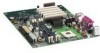
... the BIOS with the Intel® Express BIOS Update Utility With the Intel Express BIOS Update utility you can update to a new version of Windows-based installation wizards. Navigate to the Intel World Wide Web site: http://support.intel.com/support/motherboards/desktop 2. Double-click the executable file from the Web provides a simple method for the D850MV or D850MD board's BIOS. 3. Close...
... the BIOS with the Intel® Express BIOS Update Utility With the Intel Express BIOS Update utility you can update to a new version of Windows-based installation wizards. Navigate to the Intel World Wide Web site: http://support.intel.com/support/motherboards/desktop 2. Double-click the executable file from the Web provides a simple method for the D850MV or D850MD board's BIOS. 3. Close...
Product Guide
Page 44
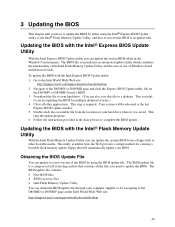
... 1. Do not interrupt the process or the system may not function. 1. During system boot, the AUTOEXEC.BAT file provided with the BIOS update diskette in the boot block area, there is unlikely that anything on the screen during this procedure. See page 37 for the ...jumper from all external peripherals. 2. The Intel Flash Memory Update Utility allows you to remove the diskette and to make sure the update was successful. As the computer boots, check the BIOS identifier (version number) to reboot the system. 3. Intel Desktop Boards D850MD and D850MV Product Guide ✏ NOTE Please review...
... 1. Do not interrupt the process or the system may not function. 1. During system boot, the AUTOEXEC.BAT file provided with the BIOS update diskette in the boot block area, there is unlikely that anything on the screen during this procedure. See page 37 for the ...jumper from all external peripherals. 2. The Intel Flash Memory Update Utility allows you to remove the diskette and to make sure the update was successful. As the computer boots, check the BIOS identifier (version number) to reboot the system. 3. Intel Desktop Boards D850MD and D850MV Product Guide ✏ NOTE Please review...

Product Guide
Page 45
...10. Drive A activity will begin again followed by two more beeps indicating the successful recovery of continuous beeps indicates a failed BIOS recovery. 7. Remove the computer cover and continue with the BIOS update (see page 44). 45 Leave the update diskette in drive A, replace the computer cover, and connect the computer's ... and disconnect its power cord. 9. In about a minute, two beeps are heard and drive A activity ceases (temporarily) indicating the successful recovery of the BIOS core. Turn on pins 1-2 as shown below to step 1 and repeat the recovery process. 8.
...10. Drive A activity will begin again followed by two more beeps indicating the successful recovery of continuous beeps indicates a failed BIOS recovery. 7. Remove the computer cover and continue with the BIOS update (see page 44). 45 Leave the update diskette in drive A, replace the computer cover, and connect the computer's ... and disconnect its power cord. 9. In about a minute, two beeps are heard and drive A activity ceases (temporarily) indicating the successful recovery of the BIOS core. Turn on pins 1-2 as shown below to step 1 and repeat the recovery process. 8.
Product Guide
Page 47
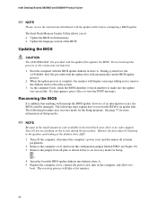
... Maintenance Main Advanced Security Power Boot Exit Table 6 shows the BIOS Setup program menu bar. 4 Using the Setup Program The BIOS Setup program can be used to the desktop boards with other BIOS identifiers might have differences in this section apply to view and ...changes to set program options * For information about the BIS, refer to the Intel Desktop Board D850MD/D850MV Technical Product Specification or the Intel World Wide Web site: http://support.intel.com/support/motherboards/desktop ✏ NOTE For reference purposes, you make changes to the settings, update...
... Maintenance Main Advanced Security Power Boot Exit Table 6 shows the BIOS Setup program menu bar. 4 Using the Setup Program The BIOS Setup program can be used to the desktop boards with other BIOS identifiers might have differences in this section apply to view and ...changes to set program options * For information about the BIS, refer to the Intel Desktop Board D850MD/D850MV Technical Product Specification or the Intel World Wide Web site: http://support.intel.com/support/motherboards/desktop ✏ NOTE For reference purposes, you make changes to the settings, update...

Product Guide
Page 48
... Invokes the Extended Configuration submenu. Displays processor information. Table 7. Table 8. Displays the processor's stepping signature. BIOS Setup Program Function Keys BIOS Setup Program Function Key or or Description Selects a different menu screen Moves cursor up or down Moves cursor to... for information about the BIS, refer to clear the Setup passwords and enable extended configuration mode. Intel Desktop Boards D850MD and D850MV Product Guide Table 7 shows the function keys available for Management Boot Integrity Service (BIS) credentials. Clears the...
... Invokes the Extended Configuration submenu. Displays processor information. Table 7. Table 8. Displays the processor's stepping signature. BIOS Setup Program Function Keys BIOS Setup Program Function Key or or Description Selects a different menu screen Moves cursor up or down Moves cursor to... for information about the BIS, refer to clear the Setup passwords and enable extended configuration mode. Intel Desktop Boards D850MD and D850MV Product Guide Table 7 shows the function keys available for Management Boot Integrity Service (BIS) credentials. Clears the...


