
Product Guide
Page 3
Contents 1 Desktop Board Features Board Components ...9 Processor ...11 Main Memory ...12 Intel® 850 Chipset ...12 Intel® 82850 Memory Controller Hub (MCH 12 Intel® 82801BA I/O Controller Hub (ICH2 13 Firmware Hub (FWH 13 Input/Output (I/O) Controller 13 Real-Time Clock...13 USB Support ...14 PCI Enhanced IDE Interface 14 Expansion Slots...14 AGP Connector ...15 Communication and...
Contents 1 Desktop Board Features Board Components ...9 Processor ...11 Main Memory ...12 Intel® 850 Chipset ...12 Intel® 82850 Memory Controller Hub (MCH 12 Intel® 82801BA I/O Controller Hub (ICH2 13 Firmware Hub (FWH 13 Input/Output (I/O) Controller 13 Real-Time Clock...13 USB Support ...14 PCI Enhanced IDE Interface 14 Expansion Slots...14 AGP Connector ...15 Communication and...

Product Guide
Page 6
... 71 27. Boot Device Priority ...63 26. System Memory Map 73 28. Beep Codes ...77 32. EMC Regulations ...81 vi Intel Desktop Boards D850MD and D850MV Product Guide 26. RJ-45 LAN Connector LEDs 17 4. Standby Current Requirements 20 5. PCI Configuration Submenu 52 13. Feature Summary ...7...Submenu 58 18. Video Configuration Submenu 59 20. Main Menu ...50 11. Power Menu...61 22. DMA Channels...73 29. Processors Supported by the Desktop Board 11 3. BIOS Error Messages 78 33. ACPI Submenu ...62 24. Exit Menu...64 27. Boot Menu ...63 25. I/O Map......
... 71 27. Boot Device Priority ...63 26. System Memory Map 73 28. Beep Codes ...77 32. EMC Regulations ...81 vi Intel Desktop Boards D850MD and D850MV Product Guide 26. RJ-45 LAN Connector LEDs 17 4. Standby Current Requirements 20 5. PCI Configuration Submenu 52 13. Feature Summary ...7...Submenu 58 18. Video Configuration Submenu 59 20. Main Menu ...50 11. Power Menu...61 22. DMA Channels...73 29. Processors Supported by the Desktop Board 11 3. BIOS Error Messages 78 33. ACPI Submenu ...62 24. Exit Menu...64 27. Boot Menu ...63 25. I/O Map......

Product Guide
Page 7
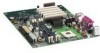
... Intel® 850 chipset, consisting of the D850MD and D850MV boards. Feature Summary Form Factors Processor Memory Chipset • microATX at 9.6 inches by 9.6 inches (D850MD board) • ATX at 9.6 inches by 12 inches (D850MV board) • Support for an Intel® Pentium® 4 processor...Intel® 82801BA I /O controller LAN Optional Intel® 82562ET 10/100 Mbit/sec Platform LAN Connect (PLC) device and RJ-45 connector Graphics Audio AGP connector supporting 1.5 V 4X or 2X AGP cards Analog Devices Inc. Table 1. 1 Desktop Board Features ✏ NOTE The D850MD board...
... Intel® 850 chipset, consisting of the D850MD and D850MV boards. Feature Summary Form Factors Processor Memory Chipset • microATX at 9.6 inches by 9.6 inches (D850MD board) • ATX at 9.6 inches by 12 inches (D850MV board) • Support for an Intel® Pentium® 4 processor...Intel® 82801BA I /O controller LAN Optional Intel® 82562ET 10/100 Mbit/sec Platform LAN Connect (PLC) device and RJ-45 connector Graphics Audio AGP connector supporting 1.5 V 4X or 2X AGP cards Analog Devices Inc. Table 1. 1 Desktop Board Features ✏ NOTE The D850MD board...
Product Guide
Page 11
... information on processor support for the D850MD and D850MV boards, refer to the Intel desktop board World Wide Web site at: http://support.intel.com/support/motherboards/desktop For instructions on installing or upgrading the processor, see Chapter 2 on page 69 show the two power connector locations. 11 Processors are needed to provide extra power to the Intel 850 chipset and Pentium 4 processor. Processors Supported by the Desktop Board Type...
... information on processor support for the D850MD and D850MV boards, refer to the Intel desktop board World Wide Web site at: http://support.intel.com/support/motherboards/desktop For instructions on installing or upgrading the processor, see Chapter 2 on page 69 show the two power connector locations. 11 Processors are needed to provide extra power to the Intel 850 chipset and Pentium 4 processor. Processors Supported by the Desktop Board Type...

Product Guide
Page 14
...; One AGP connector • One optional CNR connector (slot shared with PCI bus connector 3) The D850MV board has: • Five PCI bus add-in ports. The board supports the standard universal host controller interface (UHCI) and takes advantage of standard software drivers written to be ... between the processor and peripheral devices like hard disks, CD-ROM drives, and Iomega Zip† drives inside the computer. The interface supports: • Up to the computer without an external hub. Intel Desktop Boards D850MD and D850MV Product Guide USB Support The boards suppport up to...
...; One AGP connector • One optional CNR connector (slot shared with PCI bus connector 3) The D850MV board has: • Five PCI bus add-in ports. The board supports the standard universal host controller interface (UHCI) and takes advantage of standard software drivers written to be ... between the processor and peripheral devices like hard disks, CD-ROM drives, and Iomega Zip† drives inside the computer. The interface supports: • Up to the computer without an external hub. Intel Desktop Boards D850MD and D850MV Product Guide USB Support The boards suppport up to...

Product Guide
Page 25
... heatsink RM holes on how to install the processor fan heatsink, refer to the processor installation manual or the Intel World Wide Web site at: http://support.intel.com/support/motherboards/desktop Installing the Processor Fan Heatsink Retention Mechanism Base ✏ NOTE The following assembly operation should be performed after the desktop board is secured in "Before You Begin" on how...
... heatsink RM holes on how to install the processor fan heatsink, refer to the processor installation manual or the Intel World Wide Web site at: http://support.intel.com/support/motherboards/desktop Installing the Processor Fan Heatsink Retention Mechanism Base ✏ NOTE The following assembly operation should be performed after the desktop board is secured in "Before You Begin" on how...

Product Guide
Page 27
...processor manual or the Intel World Wide Web site at: http://support.intel.com/support/motherboards/desktop 27 Locate the processor socket and raise the socket lever completely. 3. the standby power LED should not be lit (see Figure 9). 4. Lower the lever to do so could damage the processor and the board. Install the processor...its original position. mPGA478B mPGA478B mPGA478B A Figure 9. Installing and Replacing Desktop Board Components Installing a Processor CAUTION Before installing or removing the processor, make sure that the corner with the triangle marking (A) is aligned ...
...processor manual or the Intel World Wide Web site at: http://support.intel.com/support/motherboards/desktop 27 Locate the processor socket and raise the socket lever completely. 3. the standby power LED should not be lit (see Figure 9). 4. Lower the lever to do so could damage the processor and the board. Install the processor...its original position. mPGA478B mPGA478B mPGA478B A Figure 9. Installing and Replacing Desktop Board Components Installing a Processor CAUTION Before installing or removing the processor, make sure that the corner with the triangle marking (A) is aligned ...
Product Guide
Page 28
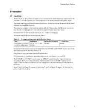
Connecting the Processor Fan Cable to the Processor Fan Connector Removing a Processor For instruction on how to remove the processor fan heatsink, refer to the processor fan connector (see Figure 10). Intel Desktop Boards D850MD and D850MV Product Guide Connecting the Processor Fan Cable Connect the processor fan cable to the processor installation manual or the Intel World Wide Web site at: http://support.intel.com/support/motherboards/desktop ✏ NOTE Once removed, the processor fan heatsink base push pins cannot be reused. 28 OM12083 Figure 10.
Connecting the Processor Fan Cable to the Processor Fan Connector Removing a Processor For instruction on how to remove the processor fan heatsink, refer to the processor fan connector (see Figure 10). Intel Desktop Boards D850MD and D850MV Product Guide Connecting the Processor Fan Cable Connect the processor fan cable to the processor installation manual or the Intel World Wide Web site at: http://support.intel.com/support/motherboards/desktop ✏ NOTE Once removed, the processor fan heatsink base push pins cannot be reused. 28 OM12083 Figure 10.

Product Guide
Page 29
Failure to the processor is for the location of sockets closest to do so could damage the memory and the board. The board supports combinations of RIMMs in the sockets in... in bank 0, install CRIMMs in the sockets in a RIMM connector can damage the D850MD and D850MV boards. When adding memory: • Install a pair of no more than 32 RDRAM components per ...module or a CRIMM module in bank 1 (see Figure 3 on page 12. Installing and Replacing Desktop Board Components Installing and Removing Memory CAUTIONS Before installing or removing RIMM modules, make sure that ac power...
Failure to the processor is for the location of sockets closest to do so could damage the memory and the board. The board supports combinations of RIMMs in the sockets in... in bank 0, install CRIMMs in the sockets in a RIMM connector can damage the D850MD and D850MV boards. When adding memory: • Install a pair of no more than 32 RDRAM components per ...module or a CRIMM module in bank 1 (see Figure 3 on page 12. Installing and Replacing Desktop Board Components Installing and Removing Memory CAUTIONS Before installing or removing RIMM modules, make sure that ac power...
Product Guide
Page 49
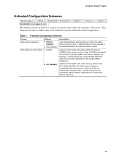
...used to memory as required. Table 9. This setting identifies the video memory range as uncacheable by the processor. Well suited for applications not supporting Write Combining. 49 If selected here, will also display in program order. Cache lookups are not performed...memory cache mode. Selects Uncacheable Speculative Write-Combining (USWC) video memory cache mode. Both the video driver and the application must support Write Combining. Extended Configuration Submenu Feature Extended Configuration Video Memory Cache Mode Options • Default (default) • User-Defined &#...
...used to memory as required. Table 9. This setting identifies the video memory range as uncacheable by the processor. Well suited for applications not supporting Write Combining. 49 If selected here, will also display in program order. Cache lookups are not performed...memory cache mode. Selects Uncacheable Speculative Write-Combining (USWC) video memory cache mode. Both the video driver and the application must support Write Combining. Extended Configuration Submenu Feature Extended Configuration Video Memory Cache Mode Options • Default (default) • User-Defined &#...
Product Guide
Page 50
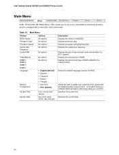
.... 50 Displays the system bus frequency. Specifies the current time. This menu reports processor and memory information and is installed, BIOS will detect and change setting to non-...used by the BIOS. Displays processor type. Displays the amount and type of RAM. Main Menu Feature BIOS Version Options No options Processor Type Processor Speed No options No options... it is ECC-capable. Displays the size of the BIOS. Displays processor operating frequency. Intel Desktop Boards D850MD and D850MV Product Guide Main Menu Maintenance Main Advanced Security Power Boot Exit Table ...
.... 50 Displays the system bus frequency. Specifies the current time. This menu reports processor and memory information and is installed, BIOS will detect and change setting to non-...used by the BIOS. Displays processor type. Displays the amount and type of RAM. Main Menu Feature BIOS Version Options No options Processor Type Processor Speed No options No options... it is ECC-capable. Displays the size of the BIOS. Displays processor operating frequency. Intel Desktop Boards D850MD and D850MV Product Guide Main Menu Maintenance Main Advanced Security Power Boot Exit Table ...

Product Guide
Page 83
...and test the desktop board, observe all of the newly completed computer. 83 If the instructions for the chassis are inconsistent with these guidelines to meet safety and regulatory requirements when installing this board assembly. If...pins on printed circuit assemblies • Rough edges and sharp corners on the chassis • Hot components (like processors, voltage regulators, and heat sinks) • Damage to wires that could be careful of noncompliance with the chassis...instructions for associated modules, contact the supplier's technical support to qualified technical personnel.
...and test the desktop board, observe all of the newly completed computer. 83 If the instructions for the chassis are inconsistent with these guidelines to meet safety and regulatory requirements when installing this board assembly. If...pins on printed circuit assemblies • Rough edges and sharp corners on the chassis • Hot components (like processors, voltage regulators, and heat sinks) • Damage to wires that could be careful of noncompliance with the chassis...instructions for associated modules, contact the supplier's technical support to qualified technical personnel.


