
Product Guide
Page 3
Contents 1 Desktop Board Features Board Components ...9 Processor ...11 Main Memory ...12 Intel® 850 Chipset ...12 Intel® 82850 Memory Controller Hub (MCH 12 Intel® 82801BA I/O Controller Hub (ICH2 13 Firmware Hub (FWH 13 Input/Output (I/O) Controller 13 Real-Time Clock...13 USB Support ...14 PCI Enhanced IDE Interface ...
Contents 1 Desktop Board Features Board Components ...9 Processor ...11 Main Memory ...12 Intel® 850 Chipset ...12 Intel® 82850 Memory Controller Hub (MCH 12 Intel® 82801BA I/O Controller Hub (ICH2 13 Firmware Hub (FWH 13 Input/Output (I/O) Controller 13 Real-Time Clock...13 USB Support ...14 PCI Enhanced IDE Interface ...

Product Guide
Page 4
Intel Desktop Boards D850MD and D850MV Product Guide Installing and Removing an AGP Card Retention Mechanism and ... the Battery ...39 3 Updating the BIOS Updating the BIOS with the Intel® Express BIOS Update Utility 43 Updating the BIOS with the Intel® Flash Memory Update Utility 43 Obtaining the BIOS Update File 43 Updating the BIOS...44...APM Submenu ...62 ACPI Submenu...62 Boot Menu...63 Boot Device Priority 63 Exit Menu ...64 5 Technical Reference Board Connectors ...65 Back Panel Connectors 66 Midboard Connectors 67 Audio Connectors 67 Power and Hardware Connectors 68 Add-In ...
Intel Desktop Boards D850MD and D850MV Product Guide Installing and Removing an AGP Card Retention Mechanism and ... the Battery ...39 3 Updating the BIOS Updating the BIOS with the Intel® Express BIOS Update Utility 43 Updating the BIOS with the Intel® Flash Memory Update Utility 43 Obtaining the BIOS Update File 43 Updating the BIOS...44...APM Submenu ...62 ACPI Submenu...62 Boot Menu...63 Boot Device Priority 63 Exit Menu ...64 5 Technical Reference Board Connectors ...65 Back Panel Connectors 66 Midboard Connectors 67 Audio Connectors 67 Power and Hardware Connectors 68 Add-In ...

Product Guide
Page 5
... 31 14. Location of the Processor Fan Heatsink Base Mounting Holes 25 8. Back Panel Connectors 66 22. Contents Desktop Board Resources 73 Memory Map ...73 DMA Channels ...73 I /O Shield 22 5. RDRAM and CRIMM Installation 29 12. AGP Card with a Retention Notch 32 ...RM Base to the Processor Fan Connector 28 11. D850MD Board Power and Hardware Control Connectors 68 24. Location of Standby Power Indicator 19 4. Installing the AGP Card Retention Mechanism 33 16. D850MV Board Components 10 3. D850MD Board Add-in Card and Peripheral Interface Connectors 70 v Connecting the...
... 31 14. Location of the Processor Fan Heatsink Base Mounting Holes 25 8. Back Panel Connectors 66 22. Contents Desktop Board Resources 73 Memory Map ...73 DMA Channels ...73 I /O Shield 22 5. RDRAM and CRIMM Installation 29 12. AGP Card with a Retention Notch 32 ...RM Base to the Processor Fan Connector 28 11. D850MD Board Power and Hardware Control Connectors 68 24. Location of Standby Power Indicator 19 4. Installing the AGP Card Retention Mechanism 33 16. D850MV Board Components 10 3. D850MD Board Add-in Card and Peripheral Interface Connectors 70 v Connecting the...

Product Guide
Page 6
.../Slave Submenus 57 17. Interrupts ...76 31. Advanced Menu ...51 12. Standby Current Requirements 20 5. Video Configuration Submenu 59 20. ACPI Submenu ...62 24. System Memory Map 73 28. DMA Channels...73 29. Maintenance Menu ...48 9. Intel Desktop Boards D850MD and D850MV Product Guide 26. Front Panel Connectors 72 Tables 1. Extended Configuration Submenu 49 10.
.../Slave Submenus 57 17. Interrupts ...76 31. Advanced Menu ...51 12. Standby Current Requirements 20 5. Video Configuration Submenu 59 20. ACPI Submenu ...62 24. System Memory Map 73 28. DMA Channels...73 29. Maintenance Menu ...48 9. Intel Desktop Boards D850MD and D850MV Product Guide 26. Front Panel Connectors 72 Tables 1. Extended Configuration Submenu 49 10.

Product Guide
Page 7
...of system memory Intel® 850 chipset, consisting of the D850MD and D850MV boards. Feature Summary Form Factors Processor Memory Chipset • microATX at 9.6 inches by 9.6 inches (D850MD board) • ATX at 9.6 inches by 12 inches (D850MV board) • Support for an Intel® ...Pentium® 4 processor in an mPGA-478 socket • 400 MHz system data bus • Four 168-pin Direct Rambus† RIMM† sockets • Support for illustrations unless otherwise noted. 1 Desktop Board Features ✏ NOTE The D850MD board...
...of system memory Intel® 850 chipset, consisting of the D850MD and D850MV boards. Feature Summary Form Factors Processor Memory Chipset • microATX at 9.6 inches by 9.6 inches (D850MD board) • ATX at 9.6 inches by 12 inches (D850MV board) • Support for an Intel® ...Pentium® 4 processor in an mPGA-478 socket • 400 MHz system data bus • Four 168-pin Direct Rambus† RIMM† sockets • Support for illustrations unless otherwise noted. 1 Desktop Board Features ✏ NOTE The D850MD board...

Product Guide
Page 8
Feature Summary (continued) BIOS • Intel/AMI BIOS • 4 Mbit symmetrical flash memory • Support for SMBIOS Power Management • Support for Advanced Configuration and Power Interface (ACPI 1.0) • Support ... activity LED connector for the front panel • Speaker ✏ NOTE For information about Intel® desktop boards, including technical product specifications, BIOS updates, and device drivers, go to the Intel World Wide Web site at: http://support.intel.com/support/motherboards/desktop 8 Intel Desktop Boards D850MD and D850MV Product Guide Table 1.
Feature Summary (continued) BIOS • Intel/AMI BIOS • 4 Mbit symmetrical flash memory • Support for SMBIOS Power Management • Support for Advanced Configuration and Power Interface (ACPI 1.0) • Support ... activity LED connector for the front panel • Speaker ✏ NOTE For information about Intel® desktop boards, including technical product specifications, BIOS updates, and device drivers, go to the Intel World Wide Web site at: http://support.intel.com/support/motherboards/desktop 8 Intel Desktop Boards D850MD and D850MV Product Guide Table 1.

Product Guide
Page 9
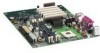
D850MD Board Components 9 Desktop Board Features Board Components Figure 1 shows the location of the major components on the D850MD board. A B CD E F G H I BB J AA K L Z Y X M W V TR US P Q O N OM11828 A ADI AD1885 audio codec P Primary IDE connector B ...connector W Speaker I Processor fan connector (CPU fan) (tachometer input) X BIOS configuration jumper J Intel 82850 Memory Controller Hub (MCH) Y SCSI hard drive activity LED connector K Processor socket Z Intel 82801BA I/O Controller Hub (ICH2) L RIMM sockets AA PCI bus add-in card connectors M RIMM ...
D850MD Board Components 9 Desktop Board Features Board Components Figure 1 shows the location of the major components on the D850MD board. A B CD E F G H I BB J AA K L Z Y X M W V TR US P Q O N OM11828 A ADI AD1885 audio codec P Primary IDE connector B ...connector W Speaker I Processor fan connector (CPU fan) (tachometer input) X BIOS configuration jumper J Intel 82850 Memory Controller Hub (MCH) Y SCSI hard drive activity LED connector K Processor socket Z Intel 82801BA I/O Controller Hub (ICH2) L RIMM sockets AA PCI bus add-in card connectors M RIMM ...

Product Guide
Page 10
... J Intel 82850 Memory Controller Hub (MCH) Y SCSI hard drive activity LED connector K Processor socket Z Intel 82801BA I/O Controller Hub (ICH2) L RIMM sockets AA PCI bus add-in card connectors M RIMM fan connector (fan 1) BB Communication and Networking Riser (CNR) N Power connector (optional) O Floppy drive connector CC Chassis fan connector (fan 3) Figure 2. Intel Desktop Boards D850MD and D850MV Product...
... J Intel 82850 Memory Controller Hub (MCH) Y SCSI hard drive activity LED connector K Processor socket Z Intel 82801BA I/O Controller Hub (ICH2) L RIMM sockets AA PCI bus add-in card connectors M RIMM fan connector (fan 1) BB Communication and Networking Riser (CNR) N Power connector (optional) O Floppy drive connector CC Chassis fan connector (fan 3) Figure 2. Intel Desktop Boards D850MD and D850MV Product...

Product Guide
Page 12
... or D850MV link on this Intel World Wide Web site: http://support.intel.com/support/motherboards/desktop For information about installing memory, see Chapter 2 on page 21. Intel® 850 Chipset The Intel 850 chipset consists of the following memory features: • Maximum of RDRAM memory • Support for a single AGP device 12 The board supports the following devices: • Intel 82850 Memory...
... or D850MV link on this Intel World Wide Web site: http://support.intel.com/support/motherboards/desktop For information about installing memory, see Chapter 2 on page 21. Intel® 850 Chipset The Intel 850 chipset consists of the following memory features: • Maximum of RDRAM memory • Support for a single AGP device 12 The board supports the following devices: • Intel 82850 Memory...
Product Guide
Page 17
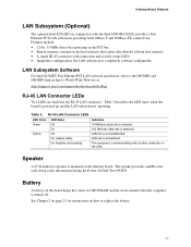
...software configurable LAN Subsystem Software For Intel 82562ET Fast Ethernet PCI LAN software and drivers, refer to the D850MD and D850MV link on the LAN. The computer is turned off. Battery A battery on the desktop board. RJ-45 LAN Connector LEDs ...intel.com/support/motherboards/desktop RJ-45 LAN Connector LEDs Two LEDs are built into the RJ-45 LAN connector. The speaker provides audible error code (beep code) information during the Power-On Self-Test (POST). LAN link is selected. Desktop Board Features LAN Subsystem (Optional) The optional Intel 82562ET (in the host memory...
...software configurable LAN Subsystem Software For Intel 82562ET Fast Ethernet PCI LAN software and drivers, refer to the D850MD and D850MV link on the LAN. The computer is turned off. Battery A battery on the desktop board. RJ-45 LAN Connector LEDs ...intel.com/support/motherboards/desktop RJ-45 LAN Connector LEDs Two LEDs are built into the RJ-45 LAN connector. The speaker provides audible error code (beep code) information during the Power-On Self-Test (POST). LAN link is selected. Desktop Board Features LAN Subsystem (Optional) The optional Intel 82562ET (in the host memory...

Product Guide
Page 18
... supply and/or affect ACPI S3 sleep state functionality. CAUTION If the standby current necessary to the system. This includes the memory modules and PCI bus connectors even when the computer appears to its last known awake state. If the system has a dual...supply must be off . When signaled by the LED turning amber. 18 Instantly Available technology enables the board to enter the ACPI S3 (Suspend-to APM support. Intel Desktop Boards D850MD and D850MV Product Guide Power Management Features Power management is implemented at several levels, including: • Software support:...
... supply and/or affect ACPI S3 sleep state functionality. CAUTION If the standby current necessary to the system. This includes the memory modules and PCI bus connectors even when the computer appears to its last known awake state. If the system has a dual...supply must be off . When signaled by the LED turning amber. 18 Instantly Available technology enables the board to enter the ACPI S3 (Suspend-to APM support. Intel Desktop Boards D850MD and D850MV Product Guide Power Management Features Power management is implemented at several levels, including: • Software support:...

Product Guide
Page 21
... using an antistatic wrist strap and a conductive foam pad. 2 Installing and Replacing Desktop Board Components This chapter tells you how to: • Install the I/O shield • Install and remove the desktop board • Install and remove a processor • Install and remove memory • Install and remove an AGP card retention mechanism and card • Connect...
... using an antistatic wrist strap and a conductive foam pad. 2 Installing and Replacing Desktop Board Components This chapter tells you how to: • Install the I/O shield • Install and remove the desktop board • Install and remove a processor • Install and remove memory • Install and remove an AGP card retention mechanism and card • Connect...

Product Guide
Page 29
...D850MV boards. The standby power indicator LED should not be the same speed (PC600 or PC800), size (64 MB, 128 MB, 256 MB, or 512 MB), and density (single- RDRAM and CRIMM Installation Bank 0 Bank 1 29 Installing and Replacing Desktop Board Components Installing and Removing Memory... CAUTIONS Before installing or removing RIMM modules, make sure that ac power has been removed by unplugging the power cord from the computer. The memory module requirements are listed in bank 1 (...
...D850MV boards. The standby power indicator LED should not be the same speed (PC600 or PC800), size (64 MB, 128 MB, 256 MB, or 512 MB), and density (single- RDRAM and CRIMM Installation Bank 0 Bank 1 29 Installing and Replacing Desktop Board Components Installing and Removing Memory... CAUTIONS Before installing or removing RIMM modules, make sure that ac power has been removed by unplugging the power cord from the computer. The memory module requirements are listed in bank 1 (...

Product Guide
Page 30
.... Bank 0 Bank 1 Bank 0 Bank 1 Bank 0 Bank 1 Bank 0 Bank 1 30 RIMM Installation • The BIOS detects the size and type of the RIMM modules in bank 0. Intel Desktop Boards D850MD and D850MV Product Guide • If memory is to be installed in bank 1, the RIMM modules to each other and match the speed of installed...
.... Bank 0 Bank 1 Bank 0 Bank 1 Bank 0 Bank 1 Bank 0 Bank 1 30 RIMM Installation • The BIOS detects the size and type of the RIMM modules in bank 0. Intel Desktop Boards D850MD and D850MV Product Guide • If memory is to be installed in bank 1, the RIMM modules to each other and match the speed of installed...

Product Guide
Page 31
... until the retaining clips snap into the socket. 6. Align the two small notches in the bottom edge of the socket. 5. Installing and Replacing Desktop Board Components To install the memory modules, follow these steps (see Figure 13): 1. Remove the computer cover. 4. Turn off the computer. Make sure the clips are pushed away from...
... until the retaining clips snap into the socket. 6. Align the two small notches in the bottom edge of the socket. 5. Installing and Replacing Desktop Board Components To install the memory modules, follow these steps (see Figure 13): 1. Remove the computer cover. 4. Turn off the computer. Make sure the clips are pushed away from...

Product Guide
Page 39
... estimated life of the battery. Brukte batterier bør kastes i henhold til gjeldende miljølovgivning. (Norwegian) VIKTIGT! Batterier bør om muligt genbruges. Installing and Replacing Desktop Board Components Replacing the Battery A coin-cell battery (CR2032) powers the real-time clock and CMOS...
... estimated life of the battery. Brukte batterier bør kastes i henhold til gjeldende miljølovgivning. (Norwegian) VIKTIGT! Batterier bør om muligt genbruges. Installing and Replacing Desktop Board Components Replacing the Battery A coin-cell battery (CR2032) powers the real-time clock and CMOS...
Product Guide
Page 43
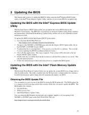
To update the BIOS with the Intel® Express BIOS Update Utility With the Intel Express BIOS Update utility you are updating the BIOS for the D850MV or D850MD board's BIOS. 3. Download the file to your hard drive. (You can obtain the BIOS update file through your ... the BIOS with the Intel® Flash Memory Update Utility With the Intel Flash Memory Update Utility you need to update the BIOS. The utility available from the location on the Intel World Wide Web site: http://support.intel.com/support/motherboards/desktop 43 Updating the BIOS with the Intel Express BIOS Update utility...
To update the BIOS with the Intel® Express BIOS Update Utility With the Intel Express BIOS Update utility you are updating the BIOS for the D850MV or D850MD board's BIOS. 3. Download the file to your hard drive. (You can obtain the BIOS update file through your ... the BIOS with the Intel® Flash Memory Update Utility With the Intel Flash Memory Update Utility you need to update the BIOS. The utility available from the location on the Intel World Wide Web site: http://support.intel.com/support/motherboards/desktop 43 Updating the BIOS with the Intel Express BIOS Update utility...
Product Guide
Page 44
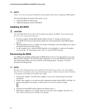
..., connect the power cord, turn on the screen during this procedure. The Intel Flash Memory Update Utility allows you to remove the diskette and to boot. Do not interrupt the process or the system may not function. 1. Intel Desktop Boards D850MD and D850MV Product Guide ✏ NOTE Please review the instructions distributed with the update files...
..., connect the power cord, turn on the screen during this procedure. The Intel Flash Memory Update Utility allows you to remove the diskette and to boot. Do not interrupt the process or the system may not function. 1. Intel Desktop Boards D850MD and D850MV Product Guide ✏ NOTE Please review the instructions distributed with the update files...
Product Guide
Page 47
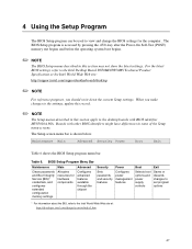
... the latest settings. Table 6. For the latest BIOS settings, refer to the Intel Desktop Board D850MD/D850MV Technical Product Specification or the Intel World Wide Web site: http://support.intel.com/support/motherboards/desktop ✏ NOTE For reference purposes, you make changes to the settings, update ...Maintenance Main Advanced Security Power Boot Exit Clears passwords and Boot Integrity Service (BIS)* credentials, and configures extended configuration memory settings Allocates resources for the computer. 4 Using the Setup Program The BIOS Setup program can be used to view...
... the latest settings. Table 6. For the latest BIOS settings, refer to the Intel Desktop Board D850MD/D850MV Technical Product Specification or the Intel World Wide Web site: http://support.intel.com/support/motherboards/desktop ✏ NOTE For reference purposes, you make changes to the settings, update ...Maintenance Main Advanced Security Power Boot Exit Clears passwords and Boot Integrity Service (BIS)* credentials, and configures extended configuration memory settings Allocates resources for the computer. 4 Using the Setup Program The BIOS Setup program can be used to view...
Product Guide
Page 49
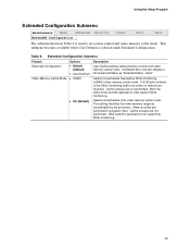
...User-Defined • USWC • UC (default) Description User-Defined allows setting memory control and video memory cache mode. Cache lookups are written to set system control and video memory cache mode. Well suited for applications not supporting Write Combining. 49 This submenu ... are not performed. Selects Uncacheable Speculative Write-Combining (USWC) video memory cache mode. Memory writes are not performed. Selects Uncacheable (UC) video memory cache mode. This setting identifies the video memory range as "Extended Menu: Used." Cache lookups are performed in ...
...User-Defined • USWC • UC (default) Description User-Defined allows setting memory control and video memory cache mode. Cache lookups are written to set system control and video memory cache mode. Well suited for applications not supporting Write Combining. 49 This submenu ... are not performed. Selects Uncacheable Speculative Write-Combining (USWC) video memory cache mode. Memory writes are not performed. Selects Uncacheable (UC) video memory cache mode. This setting identifies the video memory range as "Extended Menu: Used." Cache lookups are performed in ...


