
Product Guide
Page 5
...Heatsink RM Base to the Processor Fan Connector 28 11. D850MD Board Power and Hardware Control Connectors 68 24. Installing the I /O Map ...74 Interrupts ...76 A Error Messages and Indicators BIOS Beep Codes ...77 BIOS Error Messages ...78 B Regulatory Compliance Safety...Applications 85 Figures 1. Audio Connectors ...67 23. D850MD Board Components 9 2. Back Panel Connectors 66 22. D850MV Board Components 10 3. RIMM Installation ...30 13. D850MD Board Add-in Card and Peripheral Interface Connectors 70 v Contents Desktop Board Resources 73 Memory Map ...73 DMA Channels ...73 I...
...Heatsink RM Base to the Processor Fan Connector 28 11. D850MD Board Power and Hardware Control Connectors 68 24. Installing the I /O Map ...74 Interrupts ...76 A Error Messages and Indicators BIOS Beep Codes ...77 BIOS Error Messages ...78 B Regulatory Compliance Safety...Applications 85 Figures 1. Audio Connectors ...67 23. D850MD Board Components 9 2. Back Panel Connectors 66 22. D850MV Board Components 10 3. RIMM Installation ...30 13. D850MD Board Add-in Card and Peripheral Interface Connectors 70 v Contents Desktop Board Resources 73 Memory Map ...73 DMA Channels ...73 I...

Product Guide
Page 6
... 2. Advanced Menu ...51 12. DMA Channels...73 29. Processors Supported by the Desktop Board 11 3. Extended Configuration Submenu 49 10. APM Submenu...62 23. Beep Codes ...77 32. Intel Desktop Boards D850MD and D850MV Product Guide 26. BIOS Setup Program Menu Bar 47 7. IDE Configuration Submenu 56...RJ-45 LAN Connector LEDs 17 4. Main Menu ...50 11. Peripheral Configuration Submenu 54 15. ACPI Submenu ...62 24. D850MV Board Add-in Card and Peripheral Interface Connectors 71 27. Primary/Secondary IDE Master/Slave Submenus 57 17. Video Configuration Submenu 59 20...
... 2. Advanced Menu ...51 12. DMA Channels...73 29. Processors Supported by the Desktop Board 11 3. Extended Configuration Submenu 49 10. APM Submenu...62 23. Beep Codes ...77 32. Intel Desktop Boards D850MD and D850MV Product Guide 26. BIOS Setup Program Menu Bar 47 7. IDE Configuration Submenu 56...RJ-45 LAN Connector LEDs 17 4. Main Menu ...50 11. Peripheral Configuration Submenu 54 15. ACPI Submenu ...62 24. D850MV Board Add-in Card and Peripheral Interface Connectors 71 27. Primary/Secondary IDE Master/Slave Submenus 57 17. Video Configuration Submenu 59 20...
Product Guide
Page 17
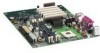
...board keeps the values in CMOS RAM and the clock current when the computer is completely software configurable LAN Subsystem Software For Intel 82562ET Fast Ethernet PCI LAN software and drivers, refer to the D850MD and D850MV link on Intel's World Wide Web site at: http://support.intel.com/support/motherboards/desktop...The speaker provides audible error code (beep code) information during the Power-On Self-Test (POST). Desktop Board Features LAN Subsystem (Optional) The optional Intel 82562ET (in conjunction with another computer on the desktop board. LAN link is established. LAN link...
...board keeps the values in CMOS RAM and the clock current when the computer is completely software configurable LAN Subsystem Software For Intel 82562ET Fast Ethernet PCI LAN software and drivers, refer to the D850MD and D850MV link on Intel's World Wide Web site at: http://support.intel.com/support/motherboards/desktop...The speaker provides audible error code (beep code) information during the Power-On Self-Test (POST). Desktop Board Features LAN Subsystem (Optional) The optional Intel 82562ET (in conjunction with another computer on the desktop board. LAN link is established. LAN link...

Product Guide
Page 45
... A, replace the computer cover, and connect the computer's power cord. 12. In about a minute, two beeps are heard and drive A activity ceases (temporarily) indicating the successful recovery of continuous beeps indicates a failed BIOS recovery. 7. This sequence of events indicates a successful BIOS recovery. • A series... 11. Drive A activity will begin to the speaker: • Upon applying power, drive A will begin again followed by two more beeps indicating the successful recovery of the boot block. If recovery is successful, turn off the computer, and disconnect its power cord. 9.
... A, replace the computer cover, and connect the computer's power cord. 12. In about a minute, two beeps are heard and drive A activity ceases (temporarily) indicating the successful recovery of continuous beeps indicates a failed BIOS recovery. 7. This sequence of events indicates a successful BIOS recovery. • A series... 11. Drive A activity will begin to the speaker: • Upon applying power, drive A will begin again followed by two more beeps indicating the successful recovery of the boot block. If recovery is successful, turn off the computer, and disconnect its power cord. 9.

Product Guide
Page 77
...POST module not found) 77 Beep Codes Number of Beeps 1 2 3 4 5 6 7 8 9 10 11 Description Refresh failure Parity cannot be toggled (memory failure or not present) Exception interrupt error Display memory R/W error (Reserved; A Error Messages and Indicators The D850MD and D850MV boards report POST errors in two ...ways: • By sounding a beep code • By displaying an error message on the monitor BIOS Beep Codes The BIOS beep codes are listed in Table 31.
...POST module not found) 77 Beep Codes Number of Beeps 1 2 3 4 5 6 7 8 9 10 11 Description Refresh failure Parity cannot be toggled (memory failure or not present) Exception interrupt error Display memory R/W error (Reserved; A Error Messages and Indicators The D850MD and D850MV boards report POST errors in two ...ways: • By sounding a beep code • By displaying an error message on the monitor BIOS Beep Codes The BIOS beep codes are listed in Table 31.


