
Product Guide
Page 3
Contents 1 Desktop Board Features Board Components ...9 Processor ...11 Main Memory ...12 Intel® 850 Chipset ...12 Intel® 82850 Memory Controller Hub (MCH 12 Intel® 82801BA I/O Controller Hub (ICH2 13 Firmware Hub (FWH 13 Input/Output (I/O) Controller 13 Real-Time Clock...13 USB Support ...14 PCI Enhanced IDE Interface ...
Contents 1 Desktop Board Features Board Components ...9 Processor ...11 Main Memory ...12 Intel® 850 Chipset ...12 Intel® 82850 Memory Controller Hub (MCH 12 Intel® 82801BA I/O Controller Hub (ICH2 13 Firmware Hub (FWH 13 Input/Output (I/O) Controller 13 Real-Time Clock...13 USB Support ...14 PCI Enhanced IDE Interface ...

Product Guide
Page 4
Intel Desktop Boards D850MD and D850MV Product Guide Installing and Removing an AGP Card Retention Mechanism... the Battery ...39 3 Updating the BIOS Updating the BIOS with the Intel® Express BIOS Update Utility 43 Updating the BIOS with the Intel® Flash Memory Update Utility 43 Obtaining the BIOS Update File 43 Updating the BIOS...44...APM Submenu ...62 ACPI Submenu...62 Boot Menu...63 Boot Device Priority 63 Exit Menu ...64 5 Technical Reference Board Connectors ...65 Back Panel Connectors 66 Midboard Connectors 67 Audio Connectors 67 Power and Hardware Connectors 68 Add-In ...
Intel Desktop Boards D850MD and D850MV Product Guide Installing and Removing an AGP Card Retention Mechanism... the Battery ...39 3 Updating the BIOS Updating the BIOS with the Intel® Express BIOS Update Utility 43 Updating the BIOS with the Intel® Flash Memory Update Utility 43 Obtaining the BIOS Update File 43 Updating the BIOS...44...APM Submenu ...62 ACPI Submenu...62 Boot Menu...63 Boot Device Priority 63 Exit Menu ...64 5 Technical Reference Board Connectors ...65 Back Panel Connectors 66 Midboard Connectors 67 Audio Connectors 67 Power and Hardware Connectors 68 Add-In ...

Product Guide
Page 5
... 14. Removing the AGP Card 34 17. D850MD Board Add-in Card and Peripheral Interface Connectors 70 v D850MD Board Mounting Screw Holes 23 6. AGP Card with a Retention Notch 32 15. D850MD Board Power and Hardware Control Connectors 68 24. D850MV Board Power and Hardware Control Connectors 69 25. Contents Desktop Board Resources 73 Memory Map ...73 DMA Channels ...73 I /O Shield...
... 14. Removing the AGP Card 34 17. D850MD Board Add-in Card and Peripheral Interface Connectors 70 v D850MD Board Mounting Screw Holes 23 6. AGP Card with a Retention Notch 32 15. D850MD Board Power and Hardware Control Connectors 68 24. D850MV Board Power and Hardware Control Connectors 69 25. Contents Desktop Board Resources 73 Memory Map ...73 DMA Channels ...73 I /O Shield...

Product Guide
Page 6
.... Beep Codes ...77 32. Intel Desktop Boards D850MD and D850MV Product Guide 26. D850MV Board Add-in Card and Peripheral Interface Connectors 71 27. Processors Supported by the Desktop Board 11 3. Jumper Settings for the BIOS Setup Program Modes (J9H2 37 6. BIOS Setup Program Menu Bar 47 7. Video Configuration Submenu 59 20. System Memory Map 73 28. Boot...
.... Beep Codes ...77 32. Intel Desktop Boards D850MD and D850MV Product Guide 26. D850MV Board Add-in Card and Peripheral Interface Connectors 71 27. Processors Supported by the Desktop Board 11 3. Jumper Settings for the BIOS Setup Program Modes (J9H2 37 6. BIOS Setup Program Menu Bar 47 7. Video Configuration Submenu 59 20. System Memory Map 73 28. Boot...

Product Guide
Page 7
... 2 GB of system memory Intel® 850 chipset, consisting of the D850MD and D850MV boards. Feature Summary Form Factors Processor Memory Chipset • microATX at 9.6 inches by 9.6 inches (D850MD board) • ATX at 9.6 inches by 12 inches (D850MV board) • Support for an Intel® Pentium®...controller LAN Optional Intel® 82562ET 10/100 Mbit/sec Platform LAN Connect (PLC) device and RJ-45 connector Graphics Audio AGP connector supporting 1.5 V 4X or 2X AGP cards Analog Devices Inc. Table 1. 1 Desktop Board Features ✏ NOTE The D850MD board layout was ...
... 2 GB of system memory Intel® 850 chipset, consisting of the D850MD and D850MV boards. Feature Summary Form Factors Processor Memory Chipset • microATX at 9.6 inches by 9.6 inches (D850MD board) • ATX at 9.6 inches by 12 inches (D850MV board) • Support for an Intel® Pentium®...controller LAN Optional Intel® 82562ET 10/100 Mbit/sec Platform LAN Connect (PLC) device and RJ-45 connector Graphics Audio AGP connector supporting 1.5 V 4X or 2X AGP cards Analog Devices Inc. Table 1. 1 Desktop Board Features ✏ NOTE The D850MD board layout was ...

Product Guide
Page 8
Intel Desktop Boards D850MD and D850MV Product Guide Table 1. Feature Summary (continued) BIOS • Intel/AMI BIOS • 4 Mbit symmetrical flash memory • Support for SMBIOS Power Management • Support for Advanced Configuration and Power Interface (ACPI 1.0) •...hard drive activity LED connector for the front panel • Speaker ✏ NOTE For information about Intel® desktop boards, including technical product specifications, BIOS updates, and device drivers, go to the Intel World Wide Web site at: http://support.intel.com/support/motherboards/desktop 8
Intel Desktop Boards D850MD and D850MV Product Guide Table 1. Feature Summary (continued) BIOS • Intel/AMI BIOS • 4 Mbit symmetrical flash memory • Support for SMBIOS Power Management • Support for Advanced Configuration and Power Interface (ACPI 1.0) •...hard drive activity LED connector for the front panel • Speaker ✏ NOTE For information about Intel® desktop boards, including technical product specifications, BIOS updates, and device drivers, go to the Intel World Wide Web site at: http://support.intel.com/support/motherboards/desktop 8

Product Guide
Page 9
...) X BIOS configuration jumper J Intel 82850 Memory Controller Hub (MCH) Y SCSI hard drive activity LED connector K Processor socket Z Intel 82801BA I/O Controller Hub (ICH2) L RIMM sockets AA PCI bus add-in card connectors M RIMM fan connector (fan 1) BB Communication and Networking Riser (CNR) N Power connector (optional) O Floppy drive connector Figure 1. D850MD Board Components 9 Desktop Board Features Board Components Figure 1 shows...
...) X BIOS configuration jumper J Intel 82850 Memory Controller Hub (MCH) Y SCSI hard drive activity LED connector K Processor socket Z Intel 82801BA I/O Controller Hub (ICH2) L RIMM sockets AA PCI bus add-in card connectors M RIMM fan connector (fan 1) BB Communication and Networking Riser (CNR) N Power connector (optional) O Floppy drive connector Figure 1. D850MD Board Components 9 Desktop Board Features Board Components Figure 1 shows...

Product Guide
Page 10
... jumper J Intel 82850 Memory Controller Hub (MCH) Y SCSI hard drive activity LED connector K Processor socket Z Intel 82801BA I/O Controller Hub (ICH2) L RIMM sockets AA PCI bus add-in card connectors M RIMM fan connector (fan 1) BB Communication and Networking Riser (CNR) N Power connector (optional) O Floppy drive connector CC Chassis fan connector (fan 3) Figure 2. Intel Desktop Boards D850MD and D850MV...
... jumper J Intel 82850 Memory Controller Hub (MCH) Y SCSI hard drive activity LED connector K Processor socket Z Intel 82801BA I/O Controller Hub (ICH2) L RIMM sockets AA PCI bus add-in card connectors M RIMM fan connector (fan 1) BB Communication and Networking Riser (CNR) N Power connector (optional) O Floppy drive connector CC Chassis fan connector (fan 3) Figure 2. Intel Desktop Boards D850MD and D850MV...

Product Guide
Page 12
... board supports the following devices: • Intel 82850 Memory Controller Hub (MCH) with AHA bus • Intel 82801BA I/O Controller Hub (ICH2) with AHA bus • Firmware Hub (FWH) Intel® 82850 Memory Controller Hub (MCH) The MCH has these memory requirements, refer to the D850MD or D850MV link on this Intel World Wide Web site: http://support.intel.com/support/motherboards/desktop...
... board supports the following devices: • Intel 82850 Memory Controller Hub (MCH) with AHA bus • Intel 82801BA I/O Controller Hub (ICH2) with AHA bus • Firmware Hub (FWH) Intel® 82850 Memory Controller Hub (MCH) The MCH has these memory requirements, refer to the D850MD or D850MV link on this Intel World Wide Web site: http://support.intel.com/support/motherboards/desktop...
Product Guide
Page 17
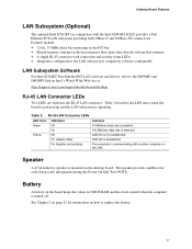
...D850MD and D850MV link on the board keeps the values in CMOS RAM and the clock current when the computer is mounted on the LAN. the LAN subsystem is communicating with another computer on the desktop board...established. Table 3. Desktop Board Features LAN Subsystem (Optional) The optional Intel 82562ET (in the host memory that copies data directly to/from host memory • A ...Intel 82562ET Fast Ethernet PCI LAN software and drivers, refer to replace the battery. 17 Battery A battery on Intel's World Wide Web site at: http://support.intel.com/support/motherboards/desktop...
...D850MD and D850MV link on the board keeps the values in CMOS RAM and the clock current when the computer is mounted on the LAN. the LAN subsystem is communicating with another computer on the desktop board...established. Table 3. Desktop Board Features LAN Subsystem (Optional) The optional Intel 82562ET (in the host memory that copies data directly to/from host memory • A ...Intel 82562ET Fast Ethernet PCI LAN software and drivers, refer to replace the battery. 17 Battery A battery on Intel's World Wide Web site at: http://support.intel.com/support/motherboards/desktop...

Product Guide
Page 18
...a wake-up device or event, the system quickly returns to provide adequate standby current when using this feature can provide ACPI support. Intel Desktop Boards D850MD and D850MV Product Guide Power Management Features Power management is implemented at several levels, including: • Software support: Advanced ...63719; Wake from USB Wake from the PCI and/or USB buses exceeds power supply capacity, the desktop board may lose register settings stored in memory. CAUTION If the standby current necessary to APM support. When signaled by the LED turning amber. 18 Failure ...
...a wake-up device or event, the system quickly returns to provide adequate standby current when using this feature can provide ACPI support. Intel Desktop Boards D850MD and D850MV Product Guide Power Management Features Power management is implemented at several levels, including: • Software support: Advanced ...63719; Wake from USB Wake from the PCI and/or USB buses exceeds power supply capacity, the desktop board may lose register settings stored in memory. CAUTION If the standby current necessary to APM support. When signaled by the LED turning amber. 18 Failure ...

Product Guide
Page 21
... configuration information. • Electrostatic discharge (ESD) can damage components. 2 Installing and Replacing Desktop Board Components This chapter tells you how to: • Install the I/O shield • Install and remove the desktop board • Install and remove a processor • Install and remove memory • Install and remove an AGP card retention mechanism and card • Connect...
... configuration information. • Electrostatic discharge (ESD) can damage components. 2 Installing and Replacing Desktop Board Components This chapter tells you how to: • Install the I/O shield • Install and remove the desktop board • Install and remove a processor • Install and remove memory • Install and remove an AGP card retention mechanism and card • Connect...

Product Guide
Page 29
... in a RIMM connector can damage the D850MD and D850MV boards. Incorrect insertion of the standby power indicator LED location). The pair of sockets closest to do so could damage the memory and the board. or double-sided). • If the desired memory configuration has been achieved in bank 0,... install CRIMMs in the sockets in bank 1 (see Figure 3 on page 12. Installing and Replacing Desktop Board Components Installing and Removing Memory CAUTIONS Before installing or removing RIMM modules, make sure that ac power has been removed by unplugging the power cord from the...
... in a RIMM connector can damage the D850MD and D850MV boards. Incorrect insertion of the standby power indicator LED location). The pair of sockets closest to do so could damage the memory and the board. or double-sided). • If the desired memory configuration has been achieved in bank 0,... install CRIMMs in the sockets in bank 1 (see Figure 3 on page 12. Installing and Replacing Desktop Board Components Installing and Removing Memory CAUTIONS Before installing or removing RIMM modules, make sure that ac power has been removed by unplugging the power cord from the...

Product Guide
Page 30
... MB RDRAM 128 MB RDRAM 512 MB RDRAM 512 MB RDRAM Figure 12. Bank 0 Bank 1 Bank 0 Bank 1 Bank 0 Bank 1 Bank 0 Bank 1 30 Intel Desktop Boards D850MD and D850MV Product Guide • If memory is to be installed in bank 0. For example, if bank 0 has two 128 MB RIMMs of PC800 RDRAM, bank 1 would require PC800... 64 MB, 128 MB, 256 MB, or 512 MB could be the same size and density to each other and match the speed of installed memory.
... MB RDRAM 128 MB RDRAM 512 MB RDRAM 512 MB RDRAM Figure 12. Bank 0 Bank 1 Bank 0 Bank 1 Bank 0 Bank 1 Bank 0 Bank 1 30 Intel Desktop Boards D850MD and D850MV Product Guide • If memory is to be installed in bank 0. For example, if bank 0 has two 128 MB RIMMs of PC800 RDRAM, bank 1 would require PC800... 64 MB, 128 MB, 256 MB, or 512 MB could be the same size and density to each other and match the speed of installed memory.

Product Guide
Page 31
.... 2. Observe the precautions in the socket. 5. When the module is seated, push down on the top edge of the module into place. Installing and Replacing Desktop Board Components To install the memory modules, follow these steps (see Figure 13): 1. Disconnect the computer's power cord from the socket. 4. Holding the...
.... 2. Observe the precautions in the socket. 5. When the module is seated, push down on the top edge of the module into place. Installing and Replacing Desktop Board Components To install the memory modules, follow these steps (see Figure 13): 1. Disconnect the computer's power cord from the socket. 4. Holding the...

Product Guide
Page 39
Installing and Replacing Desktop Board Components Replacing the Battery A coin-cell battery (CR2032) powers the real-time clock and CMOS memory. Figure 20 on hävitettävä paikallisten ympäristömääräysten mukaisesti. (Finnish) 39 Bortskaffelse af brugte batterier bør foreg&#...
Installing and Replacing Desktop Board Components Replacing the Battery A coin-cell battery (CR2032) powers the real-time clock and CMOS memory. Figure 20 on hävitettävä paikallisten ympäristömääräysten mukaisesti. (Finnish) 39 Bortskaffelse af brugte batterier bør foreg&#...
Product Guide
Page 43
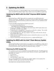
... BIOS Update window. 5. Navigate to the Intel World Wide Web site: http://support.intel.com/support/motherboards/desktop 2. Updating the BIOS with the Intel® Flash Memory Update Utility With the Intel Flash Memory Update Utility you can update the system BIOS from the Web provides a simple method for the D850MV or D850MD board's BIOS. 3. The BIOS update file is...
... BIOS Update window. 5. Navigate to the Intel World Wide Web site: http://support.intel.com/support/motherboards/desktop 2. Updating the BIOS with the Intel® Flash Memory Update Utility With the Intel Flash Memory Update Utility you can update the system BIOS from the Web provides a simple method for the D850MV or D850MD board's BIOS. 3. The BIOS update file is...
Product Guide
Page 44
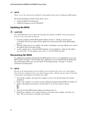
...Replace the computer cover, connect the power cord, turn on Setup modes. ✏ NOTE Because of the small amount of code available in flash memory • Update the language section of the BIOS Updating the BIOS CAUTION The AUTOEXEC.BAT file provided with the update utility before attempting a BIOS .... 3. When the update process is no video support. The following steps explain how to the speaker and looking at the diskette drive LED. 1. Intel Desktop Boards D850MD and D850MV Product Guide ✏ NOTE Please review the instructions distributed with the update files updates the BIOS.
...Replace the computer cover, connect the power cord, turn on Setup modes. ✏ NOTE Because of the small amount of code available in flash memory • Update the language section of the BIOS Updating the BIOS CAUTION The AUTOEXEC.BAT file provided with the update utility before attempting a BIOS .... 3. When the update process is no video support. The following steps explain how to the speaker and looking at the diskette drive LED. 1. Intel Desktop Boards D850MD and D850MV Product Guide ✏ NOTE Please review the instructions distributed with the update files updates the BIOS.
Product Guide
Page 47
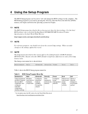
...Exit Table 6 shows the BIOS Setup program menu bar. Boards with BIOS identifier MV85010A.86A. The Setup screen menu bar is accessed by pressing the key after the Power-On Self-Test (POST) memory test begins and before the operating system boot begins. &#...or discards changes to set program options * For information about the BIS, refer to the Intel Desktop Board D850MD/D850MV Technical Product Specification or the Intel World Wide Web site: http://support.intel.com/support/motherboards/desktop ✏ NOTE For reference purposes, you make changes to the settings, update this record...
...Exit Table 6 shows the BIOS Setup program menu bar. Boards with BIOS identifier MV85010A.86A. The Setup screen menu bar is accessed by pressing the key after the Power-On Self-Test (POST) memory test begins and before the operating system boot begins. &#...or discards changes to set program options * For information about the BIS, refer to the Intel Desktop Board D850MD/D850MV Technical Product Specification or the Intel World Wide Web site: http://support.intel.com/support/motherboards/desktop ✏ NOTE For reference purposes, you make changes to the settings, update this record...
Product Guide
Page 49
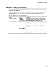
... selected under Extended Configuration. Both the video driver and the application must support Write Combining. Memory writes are written to set system control and video memory cache mode. Using the Setup Program Extended Configuration Submenu Maintenance Main Advanced Security Extended Configuration Power... Boot Exit The submenu shown in program order. This setting identifies the video memory range as "Extended Menu: Used." If selected here, will also display in the Advanced Menu as uncacheable by the ...
... selected under Extended Configuration. Both the video driver and the application must support Write Combining. Memory writes are written to set system control and video memory cache mode. Using the Setup Program Extended Configuration Submenu Maintenance Main Advanced Security Extended Configuration Power... Boot Exit The submenu shown in program order. This setting identifies the video memory range as "Extended Menu: Used." If selected here, will also display in the Advanced Menu as uncacheable by the ...


