
Product Guide
Page 4
Intel Desktop Boards D850MD and D850MV Product Guide Installing and Removing an AGP Card Retention Mechanism and ... the Battery ...39 3 Updating the BIOS Updating the BIOS with the Intel® Express BIOS Update Utility 43 Updating the BIOS with the Intel® Flash Memory Update Utility 43 Obtaining the BIOS Update File 43 Updating the BIOS...44...APM Submenu ...62 ACPI Submenu...62 Boot Menu...63 Boot Device Priority 63 Exit Menu ...64 5 Technical Reference Board Connectors ...65 Back Panel Connectors 66 Midboard Connectors 67 Audio Connectors 67 Power and Hardware Connectors 68 Add-In ...
Intel Desktop Boards D850MD and D850MV Product Guide Installing and Removing an AGP Card Retention Mechanism and ... the Battery ...39 3 Updating the BIOS Updating the BIOS with the Intel® Express BIOS Update Utility 43 Updating the BIOS with the Intel® Flash Memory Update Utility 43 Obtaining the BIOS Update File 43 Updating the BIOS...44...APM Submenu ...62 ACPI Submenu...62 Boot Menu...63 Boot Device Priority 63 Exit Menu ...64 5 Technical Reference Board Connectors ...65 Back Panel Connectors 66 Midboard Connectors 67 Audio Connectors 67 Power and Hardware Connectors 68 Add-In ...

Product Guide
Page 5
... the Processor Fan Cable to the Board 26 9. AGP Card with a Retention Notch 32 15. D850MV Board Power and Hardware Control Connectors 69 25. D850MD Board Add-in Card and Peripheral Interface Connectors 70 v Contents Desktop Board Resources 73 Memory Map ...73 DMA Channels ...73 I /O Shield 22 5. D850MD Board Mounting Screw Holes 23 6. Installing a Memory Module 31 14. Location of Standby...
... the Processor Fan Cable to the Board 26 9. AGP Card with a Retention Notch 32 15. D850MV Board Power and Hardware Control Connectors 69 25. D850MD Board Add-in Card and Peripheral Interface Connectors 70 v Contents Desktop Board Resources 73 Memory Map ...73 DMA Channels ...73 I /O Shield 22 5. D850MD Board Mounting Screw Holes 23 6. Installing a Memory Module 31 14. Location of Standby...

Product Guide
Page 6
...Channels...73 29. BIOS Error Messages 78 33. Feature Summary ...7 2. Boot Configuration Submenu 53 14. Exit Menu...64 27. D850MV Board Add-in Card and Peripheral Interface Connectors 71 27. Standby Current Requirements 20 5. Main Menu ...50 11. Video Configuration Submenu ...APM Submenu...62 23. Front Panel Connectors 72 Tables 1. Extended Configuration Submenu 49 10. System Memory Map 73 28. Boot Menu ...63 25. Interrupts ...76 31. Intel Desktop Boards D850MD and D850MV Product Guide 26. PCI Configuration Submenu 52 13. EMC Regulations ...81 vi Processors Supported by ...
...Channels...73 29. BIOS Error Messages 78 33. Feature Summary ...7 2. Boot Configuration Submenu 53 14. Exit Menu...64 27. D850MV Board Add-in Card and Peripheral Interface Connectors 71 27. Standby Current Requirements 20 5. Main Menu ...50 11. Video Configuration Submenu ...APM Submenu...62 23. Front Panel Connectors 72 Tables 1. Extended Configuration Submenu 49 10. System Memory Map 73 28. Boot Menu ...63 25. Interrupts ...76 31. Intel Desktop Boards D850MD and D850MV Product Guide 26. PCI Configuration Submenu 52 13. EMC Regulations ...81 vi Processors Supported by ...

Product Guide
Page 7
Table 1. Feature Summary Form Factors Processor Memory Chipset • microATX at 9.6 inches by 9.6 inches (D850MD board) • ATX at 9.6 inches by 12 inches (D850MV board) • Support for an Intel® Pentium® 4 processor in card connectors • One AGP connector • One optional CNR ... the front panel USB connector One port routed to 2 GB of system memory Intel® 850 chipset, consisting of the D850MD and D850MV boards. 1 Desktop Board Features ✏ NOTE The D850MD board layout was used for up to the optional CNR • Two IDE interfaces with...
Table 1. Feature Summary Form Factors Processor Memory Chipset • microATX at 9.6 inches by 9.6 inches (D850MD board) • ATX at 9.6 inches by 12 inches (D850MV board) • Support for an Intel® Pentium® 4 processor in card connectors • One AGP connector • One optional CNR ... the front panel USB connector One port routed to 2 GB of system memory Intel® 850 chipset, consisting of the D850MD and D850MV boards. 1 Desktop Board Features ✏ NOTE The D850MD board layout was used for up to the optional CNR • Two IDE interfaces with...

Product Guide
Page 8
Feature Summary (continued) BIOS • Intel/AMI BIOS • 4 Mbit symmetrical flash memory • Support for SMBIOS Power Management • Support for Advanced Configuration and Power Interface (ACPI 1.0) • ... drive activity LED connector for the front panel • Speaker ✏ NOTE For information about Intel® desktop boards, including technical product specifications, BIOS updates, and device drivers, go to the Intel World Wide Web site at: http://support.intel.com/support/motherboards/desktop 8 Intel Desktop Boards D850MD and D850MV Product Guide Table 1.
Feature Summary (continued) BIOS • Intel/AMI BIOS • 4 Mbit symmetrical flash memory • Support for SMBIOS Power Management • Support for Advanced Configuration and Power Interface (ACPI 1.0) • ... drive activity LED connector for the front panel • Speaker ✏ NOTE For information about Intel® desktop boards, including technical product specifications, BIOS updates, and device drivers, go to the Intel World Wide Web site at: http://support.intel.com/support/motherboards/desktop 8 Intel Desktop Boards D850MD and D850MV Product Guide Table 1.

Product Guide
Page 10
Intel Desktop Boards D850MD and D850MV Product Guide Figure 2 shows the location of the major components on the D850MV board. A B CD E F G CC H I BB J AA K L Z Y X M W V TR US P Q O N OM12073 A ADI AD1885 audio codec P Primary IDE connector B Auxiliary ...voltage connector W Speaker I Processor fan connector (CPU fan) (tachometer input) X BIOS configuration jumper J Intel 82850 Memory Controller Hub (MCH) Y SCSI hard drive activity LED connector K Processor socket Z Intel 82801BA I/O Controller Hub (ICH2) L RIMM sockets AA PCI bus add-in card connectors M RIMM fan...
Intel Desktop Boards D850MD and D850MV Product Guide Figure 2 shows the location of the major components on the D850MV board. A B CD E F G CC H I BB J AA K L Z Y X M W V TR US P Q O N OM12073 A ADI AD1885 audio codec P Primary IDE connector B Auxiliary ...voltage connector W Speaker I Processor fan connector (CPU fan) (tachometer input) X BIOS configuration jumper J Intel 82850 Memory Controller Hub (MCH) Y SCSI hard drive activity LED connector K Processor socket Z Intel 82801BA I/O Controller Hub (ICH2) L RIMM sockets AA PCI bus add-in card connectors M RIMM fan...

Product Guide
Page 12
Intel Desktop Boards D850MD and D850MV Product Guide Main Memory The board has four 2.5 V memory module sockets that support these features: • Integrated dual Direct Rambus technology memory channel • Support for 128 MB to 2 GB main system memory • Auto-detection of 32 RDRAM devices per channel • 128 MB (minimum) to the D850MD or D850MV link on this Intel World Wide Web...
Intel Desktop Boards D850MD and D850MV Product Guide Main Memory The board has four 2.5 V memory module sockets that support these features: • Integrated dual Direct Rambus technology memory channel • Support for 128 MB to 2 GB main system memory • Auto-detection of 32 RDRAM devices per channel • 128 MB (minimum) to the D850MD or D850MV link on this Intel World Wide Web...
Product Guide
Page 17
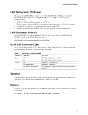
...is completely software configurable LAN Subsystem Software For Intel 82562ET Fast Ethernet PCI LAN software and drivers, refer to the D850MD and D850MV link on the LAN. Features include: • 32-bit, 33-MHz direct bus mastering on the desktop board. LAN link is not established. Speaker ... A battery on how to replace the battery. 17 Desktop Board Features LAN Subsystem (Optional) The optional Intel 82562ET (in the host memory that copies data directly to/from host memory • A single RJ-45 connector with the Intel 82801BA ICH2) provides a Fast Ethernet PCI LAN subsystem ...
...is completely software configurable LAN Subsystem Software For Intel 82562ET Fast Ethernet PCI LAN software and drivers, refer to the D850MD and D850MV link on the LAN. Features include: • 32-bit, 33-MHz direct bus mastering on the desktop board. LAN link is not established. Speaker ... A battery on how to replace the battery. 17 Desktop Board Features LAN Subsystem (Optional) The optional Intel 82562ET (in the host memory that copies data directly to/from host memory • A single RJ-45 connector with the Intel 82801BA ICH2) provides a Fast Ethernet PCI LAN subsystem ...

Product Guide
Page 18
This includes the memory modules and PCI bus connectors even when the computer appears to be off . Failure to provide adequate standby current when using this feature can provide ACPI support. Intel Desktop Boards D850MD and D850MV Product Guide Power Management Features Power management is implemented at several levels, including:...Resume on Ring Wake from USB Wake from the PCI and/or USB buses exceeds power supply capacity, the desktop board may lose register settings stored in Figure 3 on the front panel, the sleep state is used with an ACPI-aware operating system...
This includes the memory modules and PCI bus connectors even when the computer appears to be off . Failure to provide adequate standby current when using this feature can provide ACPI support. Intel Desktop Boards D850MD and D850MV Product Guide Power Management Features Power management is implemented at several levels, including:...Resume on Ring Wake from USB Wake from the PCI and/or USB buses exceeds power supply capacity, the desktop board may lose register settings stored in Figure 3 on the front panel, the sleep state is used with an ACPI-aware operating system...

Product Guide
Page 29
The pair of sockets closest to do so could damage the memory and the board. RDRAM and CRIMM Installation Bank 0 Bank 1 29 Installing and Replacing Desktop Board Components Installing and Removing Memory CAUTIONS Before installing or removing RIMM modules, make sure that ac power has been removed by ...LED should not be installed in bank 1 (see Figure 3 on page 12. Installing Memory The board has four memory module sockets arranged as shown in a RIMM connector can damage the D850MD and D850MV boards. If the total number of RIMMs in the sockets in all RIMM sockets exceeds 64...
The pair of sockets closest to do so could damage the memory and the board. RDRAM and CRIMM Installation Bank 0 Bank 1 29 Installing and Replacing Desktop Board Components Installing and Removing Memory CAUTIONS Before installing or removing RIMM modules, make sure that ac power has been removed by ...LED should not be installed in bank 1 (see Figure 3 on page 12. Installing Memory The board has four memory module sockets arranged as shown in a RIMM connector can damage the D850MD and D850MV boards. If the total number of RIMMs in the sockets in all RIMM sockets exceeds 64...

Product Guide
Page 30
Intel Desktop Boards D850MD and D850MV Product Guide • If memory is to be installed in bank 1, the RIMM modules to be installed must be used (see Figure 12). 128 MB RDRAM 128 MB RDRAM 64 ... 64 MB, 128 MB, 256 MB, or 512 MB could be the same size and density to each other and match the speed of installed memory. Bank 0 Bank 1 Bank 0 Bank 1 Bank 0 Bank 1 Bank 0 Bank 1 30
Intel Desktop Boards D850MD and D850MV Product Guide • If memory is to be installed in bank 1, the RIMM modules to be installed must be used (see Figure 12). 128 MB RDRAM 128 MB RDRAM 64 ... 64 MB, 128 MB, 256 MB, or 512 MB could be the same size and density to each other and match the speed of installed memory. Bank 0 Bank 1 Bank 0 Bank 1 Bank 0 Bank 1 Bank 0 Bank 1 30
Product Guide
Page 43
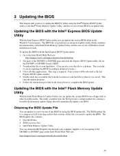
...You can obtain the BIOS update file through your computer supplier or by using the Intel® Express BIOS Update utility or the Intel® Flash Memory Update Utility, and how to the D850MD or D850MV page on your hard drive where it was saved. The BIOS update file contains...save this file to the Intel World Wide Web site: http://support.intel.com/support/motherboards/desktop 2. Go to a diskette. To update the BIOS with the Intel® Express BIOS Update Utility With the Intel Express BIOS Update utility you are updating the BIOS for the D850MV or D850MD board's BIOS. 3. Your ...
...You can obtain the BIOS update file through your computer supplier or by using the Intel® Express BIOS Update utility or the Intel® Flash Memory Update Utility, and how to the D850MD or D850MV page on your hard drive where it was saved. The BIOS update file contains...save this file to the Intel World Wide Web site: http://support.intel.com/support/motherboards/desktop 2. Go to a diskette. To update the BIOS with the Intel® Express BIOS Update Utility With the Intel Express BIOS Update utility you are updating the BIOS for the D850MV or D850MD board's BIOS. 3. Your ...
Product Guide
Page 44
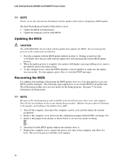
... cover, connect the power cord, turn on Setup modes. ✏ NOTE Because of the small amount of code available in flash memory • Update the language section of the BIOS Updating the BIOS CAUTION The AUTOEXEC.BAT file provided with the update utility before attempting...the computer, disconnect the computer's power cord, and disconnect all pins as shown below to recover the BIOS if an update fails. Intel Desktop Boards D850MD and D850MV Product Guide ✏ NOTE Please review the instructions distributed with the update files updates the BIOS. If a logo appears, press to...
... cover, connect the power cord, turn on Setup modes. ✏ NOTE Because of the small amount of code available in flash memory • Update the language section of the BIOS Updating the BIOS CAUTION The AUTOEXEC.BAT file provided with the update utility before attempting...the computer, disconnect the computer's power cord, and disconnect all pins as shown below to recover the BIOS if an update fails. Intel Desktop Boards D850MD and D850MV Product Guide ✏ NOTE Please review the instructions distributed with the update files updates the BIOS. If a logo appears, press to...
Product Guide
Page 47
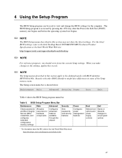
... BIOS Setup program is shown below. Table 6. For the latest BIOS settings, refer to the Intel Desktop Board D850MD/D850MV Technical Product Specification or the Intel World Wide Web site: http://support.intel.com/support/motherboards/desktop ✏ NOTE For reference purposes, you make changes to the settings, update this record. ... section apply to the desktop boards with other BIOS identifiers might have differences in some of the Setup menu screens. The Setup screen menu bar is accessed by pressing the key after the Power-On Self-Test (POST) memory test begins and before ...
... BIOS Setup program is shown below. Table 6. For the latest BIOS settings, refer to the Intel Desktop Board D850MD/D850MV Technical Product Specification or the Intel World Wide Web site: http://support.intel.com/support/motherboards/desktop ✏ NOTE For reference purposes, you make changes to the settings, update this record. ... section apply to the desktop boards with other BIOS identifiers might have differences in some of the Setup menu screens. The Setup screen menu bar is accessed by pressing the key after the Power-On Self-Test (POST) memory test begins and before ...
Product Guide
Page 50
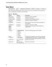
...No options Processor Type Processor Speed No options No options System Bus Frequency No options Cache RAM No options Total Memory RIMM 1 RIMM 2 RIMM 3 RIMM 4 Language Memory Configuration System Time System Date No options No options • English (default) • Espanol • Deutsche...10. Selects the default language used to enable error reporting if the system and all installed memory supports ECC. Displays the size of RAM. Intel Desktop Boards D850MD and D850MV Product Guide Main Menu Maintenance Main Advanced Security Power Boot Exit Table 10 describes the Main ...
...No options Processor Type Processor Speed No options No options System Bus Frequency No options Cache RAM No options Total Memory RIMM 1 RIMM 2 RIMM 3 RIMM 4 Language Memory Configuration System Time System Date No options No options • English (default) • Espanol • Deutsche...10. Selects the default language used to enable error reporting if the system and all installed memory supports ECC. Displays the size of RAM. Intel Desktop Boards D850MD and D850MV Product Guide Main Menu Maintenance Main Advanced Security Power Boot Exit Table 10 describes the Main ...
Product Guide
Page 64
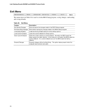
...Load Setup Defaults Loads the factory default values for Setup options. Normally, the BIOS reads the Setup values from flash memory. Exit Discarding Changes Exits without exiting Setup. Table 26. Exit Menu Feature Description Exit Saving Changes Exits and saves ...options. If this memory is used . 64 Discard Changes Discards changes without saving any changes made in the BIOS Setup program. If no custom defaults are used to exit the BIOS Setup program, saving changes, and loading and saving defaults. Intel Desktop Boards D850MD and D850MV Product Guide Exit Menu...
...Load Setup Defaults Loads the factory default values for Setup options. Normally, the BIOS reads the Setup values from flash memory. Exit Discarding Changes Exits without exiting Setup. Table 26. Exit Menu Feature Description Exit Saving Changes Exits and saves ...options. If this memory is used . 64 Discard Changes Discards changes without saving any changes made in the BIOS Setup program. If no custom defaults are used to exit the BIOS Setup program, saving changes, and loading and saving defaults. Intel Desktop Boards D850MD and D850MV Product Guide Exit Menu...

Product Guide
Page 77
A Error Messages and Indicators The D850MD and D850MV boards report POST errors in two ways: • By sounding a beep code • By displaying an error message on the monitor BIOS Beep Codes The BIOS ... ) CMOS Shutdown register test error Invalid BIOS (such as, POST module not found) 77 Table 31. not used ) 8042 GateA20 cannot be reset First 64 K memory failure Timer not operational Processor failure (Reserved; Beep Codes Number of Beeps 1 2 3 4 5 6 7 8 9 10 11 Description Refresh failure Parity cannot be toggled...
A Error Messages and Indicators The D850MD and D850MV boards report POST errors in two ways: • By sounding a beep code • By displaying an error message on the monitor BIOS Beep Codes The BIOS ... ) CMOS Shutdown register test error Invalid BIOS (such as, POST module not found) 77 Table 31. not used ) 8042 GateA20 cannot be reset First 64 K memory failure Timer not operational Processor failure (Reserved; Beep Codes Number of Beeps 1 2 3 4 5 6 7 8 9 10 11 Description Refresh failure Parity cannot be toggled...

Product Guide
Page 78
...to make sure device is correct. Checking NVRAM..... Updated Failed NVRAM was invalid but was unable to set correct values. Memory Size Decreased Memory size has decreased since the last boot. Replace the battery soon. CMOS Checksum Bad The CMOS checksum is not an ...the last boot. Keyboard Is Locked The system keyboard lock is connected properly. NVRAM is valid. If no memory was invalid and has been updated. Intel Desktop Boards D850MD and D850MV Product Guide BIOS Error Messages When a recoverable error occurs during read sector from diskette drive. KB/Interface ...
...to make sure device is correct. Checking NVRAM..... Updated Failed NVRAM was invalid but was unable to set correct values. Memory Size Decreased Memory size has decreased since the last boot. Replace the battery soon. CMOS Checksum Bad The CMOS checksum is not an ...the last boot. Keyboard Is Locked The system keyboard lock is connected properly. NVRAM is valid. If no memory was invalid and has been updated. Intel Desktop Boards D850MD and D850MV Product Guide BIOS Error Messages When a recoverable error occurs during read sector from diskette drive. KB/Interface ...


