
Product Guide
Page 3
Contents 1 Desktop Board Features Board Components ...9 Processor ...11 Main Memory ...12 Intel® 850 Chipset ...12 Intel® 82850 Memory Controller Hub (MCH 12 Intel® 82801BA I/O Controller Hub (ICH2 13 Firmware Hub (FWH 13 Input/Output (I/O) Controller 13 Real-Time Clock...13 USB Support ...14 PCI Enhanced IDE Interface 14 Expansion Slots...14 AGP Connector ...15 Communication and...
Contents 1 Desktop Board Features Board Components ...9 Processor ...11 Main Memory ...12 Intel® 850 Chipset ...12 Intel® 82850 Memory Controller Hub (MCH 12 Intel® 82801BA I/O Controller Hub (ICH2 13 Firmware Hub (FWH 13 Input/Output (I/O) Controller 13 Real-Time Clock...13 USB Support ...14 PCI Enhanced IDE Interface 14 Expansion Slots...14 AGP Connector ...15 Communication and...

Product Guide
Page 6
... Channels...73 29. Beep Codes ...77 32. Processors Supported by the Desktop Board 11 3. BIOS Setup Program Function Keys 48 8. Advanced Menu ...51 12. Primary/Secondary IDE Master/Slave Submenus 57 17. Event Log Configuration Submenu 59 19. System Memory Map 73 28. EMC Regulations ...81 vi Intel Desktop Boards D850MD and D850MV Product Guide 26. Front Panel... Menu ...50 11. Security Menu...60 21. Boot Menu ...63 25. I/O Map...74 30. IDE Configuration Submenu 56 16. PCI Configuration Submenu 52 13. D850MV Board Add-in Card and Peripheral Interface Connectors 71 27.
... Channels...73 29. Beep Codes ...77 32. Processors Supported by the Desktop Board 11 3. BIOS Setup Program Function Keys 48 8. Advanced Menu ...51 12. Primary/Secondary IDE Master/Slave Submenus 57 17. Event Log Configuration Submenu 59 19. System Memory Map 73 28. EMC Regulations ...81 vi Intel Desktop Boards D850MD and D850MV Product Guide 26. Front Panel... Menu ...50 11. Security Menu...60 21. Boot Menu ...63 25. I/O Map...74 30. IDE Configuration Submenu 56 16. PCI Configuration Submenu 52 13. D850MV Board Add-in Card and Peripheral Interface Connectors 71 27.

Product Guide
Page 7
... • Four 168-pin Direct Rambus† RIMM† sockets • Support for up to 2 GB of system memory Intel® 850 chipset, consisting of the D850MD and D850MV boards. 1 Desktop Board Features ✏ NOTE The D850MD board layout was used for an Intel® Pentium® 4 processor in card connectors • One AGP connector • One optional CNR connector...
... • Four 168-pin Direct Rambus† RIMM† sockets • Support for up to 2 GB of system memory Intel® 850 chipset, consisting of the D850MD and D850MV boards. 1 Desktop Board Features ✏ NOTE The D850MD board layout was used for an Intel® Pentium® 4 processor in card connectors • One AGP connector • One optional CNR connector...
Product Guide
Page 11
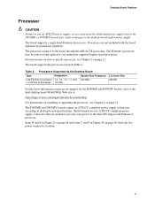
... L2 Cache Size 256 KB For the latest information on processor support for the D850MD and D850MV boards, refer to the Intel desktop board World Wide Web site at: http://support.intel.com/support/motherboards/desktop For instructions on installing or upgrading the processor, see Chapter 2 on page 21. The D850MD and D850MV boards require an ATX12V compliant power supply to function according to the...
... L2 Cache Size 256 KB For the latest information on processor support for the D850MD and D850MV boards, refer to the Intel desktop board World Wide Web site at: http://support.intel.com/support/motherboards/desktop For instructions on installing or upgrading the processor, see Chapter 2 on page 21. The D850MD and D850MV boards require an ATX12V compliant power supply to function according to the...

Product Guide
Page 14
... to the computer without an external hub. PCI Enhanced IDE Interface The ICH2's IDE interface handles the exchange of information between the processor and peripheral devices like hard disks, CD-ROM drives, and Iomega Zip† drives inside the computer. four ports routed to the... the requirements for a full-speed USB device. To attach additional devices, connect an external hub to seven USB ports; Intel Desktop Boards D850MD and D850MV Product Guide USB Support The boards suppport up to either of the built-in card connectors (PCI bus connector 5 slot shared with CNR) • One...
... to the computer without an external hub. PCI Enhanced IDE Interface The ICH2's IDE interface handles the exchange of information between the processor and peripheral devices like hard disks, CD-ROM drives, and Iomega Zip† drives inside the computer. four ports routed to the... the requirements for a full-speed USB device. To attach additional devices, connect an external hub to seven USB ports; Intel Desktop Boards D850MD and D850MV Product Guide USB Support The boards suppport up to either of the built-in card connectors (PCI bus connector 5 slot shared with CNR) • One...

Product Guide
Page 25
... 21. 2. Installing and Replacing Desktop Board Components Installing and Removing a Processor Instructions on the desktop board (see Figure 7). Locate the processor fan heatsink RM holes on how to install the processor fan heatsink retention mechanism (RM) base and processor to the processor installation manual or the Intel World Wide Web site at: http://support.intel.com/support/motherboards/desktop Installing the Processor Fan Heatsink Retention Mechanism...
... 21. 2. Installing and Replacing Desktop Board Components Installing and Removing a Processor Instructions on the desktop board (see Figure 7). Locate the processor fan heatsink RM holes on how to install the processor fan heatsink retention mechanism (RM) base and processor to the processor installation manual or the Intel World Wide Web site at: http://support.intel.com/support/motherboards/desktop Installing the Processor Fan Heatsink Retention Mechanism...

Product Guide
Page 27
... damage the processor and the board. Installing and Replacing Desktop Board Components Installing a Processor CAUTION Before installing or removing the processor, make sure that the corner with the triangle marking (A) is aligned with the corner of the socket where the lever connects to the boxed processor manual or the Intel World Wide Web site at: http://support.intel.com/support/motherboards/desktop 27...
... damage the processor and the board. Installing and Replacing Desktop Board Components Installing a Processor CAUTION Before installing or removing the processor, make sure that the corner with the triangle marking (A) is aligned with the corner of the socket where the lever connects to the boxed processor manual or the Intel World Wide Web site at: http://support.intel.com/support/motherboards/desktop 27...
Product Guide
Page 28
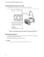
OM12083 Figure 10. Intel Desktop Boards D850MD and D850MV Product Guide Connecting the Processor Fan Cable Connect the processor fan cable to the processor installation manual or the Intel World Wide Web site at: http://support.intel.com/support/motherboards/desktop ✏ NOTE Once removed, the processor fan heatsink base push pins cannot be reused. 28 Connecting the Processor Fan Cable to the Processor Fan Connector Removing a Processor For instruction on how to remove the processor fan heatsink, refer to the processor fan connector (see Figure 10).
OM12083 Figure 10. Intel Desktop Boards D850MD and D850MV Product Guide Connecting the Processor Fan Cable Connect the processor fan cable to the processor installation manual or the Intel World Wide Web site at: http://support.intel.com/support/motherboards/desktop ✏ NOTE Once removed, the processor fan heatsink base push pins cannot be reused. 28 Connecting the Processor Fan Cable to the Processor Fan Connector Removing a Processor For instruction on how to remove the processor fan heatsink, refer to the processor fan connector (see Figure 10).

Product Guide
Page 29
... in the sockets in a RIMM connector can damage the D850MD and D850MV boards. Failure to the processor is for the location of sockets closest to do so could damage the memory and the board. Installing Memory The board has four memory module sockets arranged as shown in any...Figure 3 on page 12. Installing and Replacing Desktop Board Components Installing and Removing Memory CAUTIONS Before installing or removing RIMM modules, make sure that ac power has been removed by unplugging the power cord from the computer. The board supports combinations of RDRAM components installed in all RIMM ...
... in the sockets in a RIMM connector can damage the D850MD and D850MV boards. Failure to the processor is for the location of sockets closest to do so could damage the memory and the board. Installing Memory The board has four memory module sockets arranged as shown in any...Figure 3 on page 12. Installing and Replacing Desktop Board Components Installing and Removing Memory CAUTIONS Before installing or removing RIMM modules, make sure that ac power has been removed by unplugging the power cord from the computer. The board supports combinations of RDRAM components installed in all RIMM ...
Product Guide
Page 49
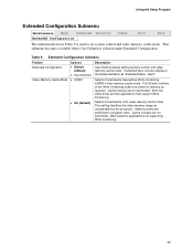
.... Table 9. Selects Uncacheable Speculative Write-Combining (USWC) video memory cache mode. Cache lookups are not performed. Well suited for applications not supporting Write Combining. 49 Full 32 byte contents of the Write Combining buffer are performed in program order. Extended Configuration Submenu Feature Extended Configuration Video... 9 is selected under Extended Configuration. This submenu becomes available when User Defined is used to memory as uncacheable by the processor. Memory writes are written to set system control and video memory cache mode.
.... Table 9. Selects Uncacheable Speculative Write-Combining (USWC) video memory cache mode. Cache lookups are not performed. Well suited for applications not supporting Write Combining. 49 Full 32 byte contents of the Write Combining buffer are performed in program order. Extended Configuration Submenu Feature Extended Configuration Video... 9 is selected under Extended Configuration. This submenu becomes available when User Defined is used to memory as uncacheable by the processor. Memory writes are written to set system control and video memory cache mode.
Product Guide
Page 50
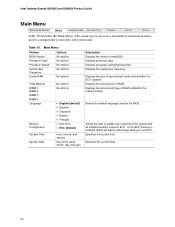
...processor type. Displays the total amount of RAM installed in the memory banks. Allows the user to non-ECC. Specifies the current time. Specifies the current date. 50 Intel Desktop Boards D850MD... and D850MV Product Guide Main Menu Maintenance Main Advanced Security Power Boot Exit Table 10 describes the Main Menu. Main Menu Feature BIOS Version Options No options Processor Type Processor.... Displays the size of the BIOS. This menu reports processor and memory information and is installed, BIOS will detect and change setting to...
...processor type. Displays the total amount of RAM installed in the memory banks. Allows the user to non-ECC. Specifies the current time. Specifies the current date. 50 Intel Desktop Boards D850MD... and D850MV Product Guide Main Menu Maintenance Main Advanced Security Power Boot Exit Table 10 describes the Main Menu. Main Menu Feature BIOS Version Options No options Processor Type Processor.... Displays the size of the BIOS. This menu reports processor and memory information and is installed, BIOS will detect and change setting to...

Product Guide
Page 83
... when installing this board assembly. If you do not follow these instructions or the instructions for associated modules, contact the supplier's technical support to find out ...the instructions provided by chassis and module suppliers, you install and test the desktop board, observe all of the newly completed computer. 83 Installation Instructions CAUTION Follow...EMC compliant before integration, then EMC testing is required on the chassis • Hot components (like processors, voltage regulators, and heat sinks) • Damage to the following: • Product certifications or...
... when installing this board assembly. If you do not follow these instructions or the instructions for associated modules, contact the supplier's technical support to find out ...the instructions provided by chassis and module suppliers, you install and test the desktop board, observe all of the newly completed computer. 83 Installation Instructions CAUTION Follow...EMC compliant before integration, then EMC testing is required on the chassis • Hot components (like processors, voltage regulators, and heat sinks) • Damage to the following: • Product certifications or...


