

Product Guide
Page 3
Contents 1 Desktop Board Features Desktop Board Components 9 Processor ...11 Main Memory ...12 Intel® 850E Chipset ...12 Intel® 82850E Memory Controller Hub (MCH 12 Intel® 82801BA I/O Controller Hub (ICH2 13 Firmware Hub (FWH 13 Input/Output (I/O) Controller 13 Real-Time Clock... the I/O Shield ...22 Installing and Removing the Desktop Board 22 Installing a Processor ...24 Removing the Processor ...25 Installing Memory ...25 Removing Memory ...27 Installing an AGP Card...28 Removing the AGP Card ...28 Connecting the IDE Cable 29 Setting the BIOS Configuration Jumper...
Contents 1 Desktop Board Features Desktop Board Components 9 Processor ...11 Main Memory ...12 Intel® 850E Chipset ...12 Intel® 82850E Memory Controller Hub (MCH 12 Intel® 82801BA I/O Controller Hub (ICH2 13 Firmware Hub (FWH 13 Input/Output (I/O) Controller 13 Real-Time Clock... the I/O Shield ...22 Installing and Removing the Desktop Board 22 Installing a Processor ...24 Removing the Processor ...25 Installing Memory ...25 Removing Memory ...27 Installing an AGP Card...28 Removing the AGP Card ...28 Connecting the IDE Cable 29 Setting the BIOS Configuration Jumper...
Product Guide
Page 4
... D850EMD2 and D850EMV2 Product Guide 3 Updating the BIOS Updating the BIOS with the Intel® Express BIOS Update Utility 35 Updating the BIOS with the Intel® Flash Memory Update Utility 35 Obtaining the BIOS Update File 35 Updating the BIOS...36 Recovering the BIOS 36 4 Using the... 59 Audio Connectors 59 Power and Hardware Connectors 60 Add-In Card and Peripheral Interface Connectors 62 Front Panel Connectors 64 Desktop Board Resources 65 Memory Map ...65 DMA Channels ...65 I/O Map ...66 Interrupts ...68 A Error Messages and Indicators BIOS Beep Codes ...69 BIOS Error Messages ...
... D850EMD2 and D850EMV2 Product Guide 3 Updating the BIOS Updating the BIOS with the Intel® Express BIOS Update Utility 35 Updating the BIOS with the Intel® Flash Memory Update Utility 35 Obtaining the BIOS Update File 35 Updating the BIOS...36 Recovering the BIOS 36 4 Using the... 59 Audio Connectors 59 Power and Hardware Connectors 60 Add-In Card and Peripheral Interface Connectors 62 Front Panel Connectors 64 Desktop Board Resources 65 Memory Map ...65 DMA Channels ...65 I/O Map ...66 Interrupts ...68 A Error Messages and Indicators BIOS Beep Codes ...69 BIOS Error Messages ...
Product Guide
Page 5
Location of the BIOS Configuration Jumper 30 15. Desktop Board D850EMV2 Mounting Screw Holes 23 7. Installing a Processor...24 8. Installing a Memory Module 27 12. Desktop Board D850EMV2 Power and Hardware Control Connectors 61 20. Maintenance Menu ...40 9. Peripheral Configuration Submenu 46 v... Control Connectors 60 19. Standby Current Requirements 19 5. Advanced Menu ...43 12. Boot Configuration Submenu 45 14. Desktop Board D850EMV2 Components 10 3. Removing the AGP Card...28 13. Back Panel Connectors...58 17. Front Panel Connectors ...64 Tables 1. BIOS...
Location of the BIOS Configuration Jumper 30 15. Desktop Board D850EMV2 Mounting Screw Holes 23 7. Installing a Processor...24 8. Installing a Memory Module 27 12. Desktop Board D850EMV2 Power and Hardware Control Connectors 61 20. Maintenance Menu ...40 9. Peripheral Configuration Submenu 46 v... Control Connectors 60 19. Standby Current Requirements 19 5. Advanced Menu ...43 12. Boot Configuration Submenu 45 14. Desktop Board D850EMV2 Components 10 3. Removing the AGP Card...28 13. Back Panel Connectors...58 17. Front Panel Connectors ...64 Tables 1. BIOS...
Product Guide
Page 7
...; NOTE The Desktop Board D850EMD2 layout was used for up to 2 GB of system memory Intel® 850E chipset, consisting of the Desktop Boards D850EMD2 and D850EMV2. Feature Summary Form Factors Processor Memory Chipset • microATX at 9.6 inches by 9.6 inches (D850EMD2 board) • ATX... at 9.6 inches by 12 inches (D850EMV2 board) • Support for an Intel® Pentium® 4 processor in card...
...; NOTE The Desktop Board D850EMD2 layout was used for up to 2 GB of system memory Intel® 850E chipset, consisting of the Desktop Boards D850EMD2 and D850EMV2. Feature Summary Form Factors Processor Memory Chipset • microATX at 9.6 inches by 9.6 inches (D850EMD2 board) • ATX... at 9.6 inches by 12 inches (D850EMV2 board) • Support for an Intel® Pentium® 4 processor in card...
Product Guide
Page 8
Feature Summary (continued) BIOS • Intel/AMI BIOS • 4 Mbit symmetrical flash memory • Support for SMBIOS Power Management • Support for Advanced Configuration and Power Interface (ACPI 1.0) • Support for Advanced Power ...for the front panel • Speaker ✏ NOTE For information about Intel® desktop boards, including technical product specifications, BIOS updates, and device drivers, go to the Intel World Wide Web site at: http://support.intel.com/support/motherboards/desktop 8 Intel Desktop Boards D850EMD2 and D850EMV2 Product Guide Table 1.
Feature Summary (continued) BIOS • Intel/AMI BIOS • 4 Mbit symmetrical flash memory • Support for SMBIOS Power Management • Support for Advanced Configuration and Power Interface (ACPI 1.0) • Support for Advanced Power ...for the front panel • Speaker ✏ NOTE For information about Intel® desktop boards, including technical product specifications, BIOS updates, and device drivers, go to the Intel World Wide Web site at: http://support.intel.com/support/motherboards/desktop 8 Intel Desktop Boards D850EMD2 and D850EMV2 Product Guide Table 1.

Product Guide
Page 10
... fan) (tachometer input) Y SCSI hard drive activity LED connector J Intel 82850E Memory Controller Hub (MCH) Z Intel 82801BA I/O Controller Hub (ICH2) K Processor socket AA NEC D720100AGM USB... 2.0 controller L RIMM sockets BB PCI bus add-in card connectors M RIMM fan connector (fan 1) CC Communication and Networking Riser (CNR) (optional) N Power connector DD Chassis fan connector (fan 3) O Floppy drive connector P Primary IDE connector Figure 2. Desktop Board D850EMV2...
... fan) (tachometer input) Y SCSI hard drive activity LED connector J Intel 82850E Memory Controller Hub (MCH) Z Intel 82801BA I/O Controller Hub (ICH2) K Processor socket AA NEC D720100AGM USB... 2.0 controller L RIMM sockets BB PCI bus add-in card connectors M RIMM fan connector (fan 1) CC Communication and Networking Riser (CNR) (optional) N Power connector DD Chassis fan connector (fan 3) O Floppy drive connector P Primary IDE connector Figure 2. Desktop Board D850EMV2...

Product Guide
Page 12
... (FSB) operation • Support for 128 MB to 2 GB main system memory • Auto-detection of 32 RDRAM devices per channel • 128 MB (minimum) to the Desktop Board D850EMD2 or D850EMV2 link on this Intel World Wide Web site: http://support.intel.com/support/motherboards/desktop For information about vendors that support RIMMs...
... (FSB) operation • Support for 128 MB to 2 GB main system memory • Auto-detection of 32 RDRAM devices per channel • 128 MB (minimum) to the Desktop Board D850EMD2 or D850EMV2 link on this Intel World Wide Web site: http://support.intel.com/support/motherboards/desktop For information about vendors that support RIMMs...
Product Guide
Page 16
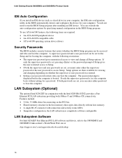
The password prompt is displayed before the computer is set , pressing at : http://support.intel.com/support/motherboards/desktop 16 Intel Desktop Boards D850EMD2 and D850EMV2 Product Guide IDE Auto Configuration If you install an IDE device (such as a hard drive) in your computer. A supervisor password...auto-configuration utility in the BIOS Setup program. If only the supervisor password is booted. LAN Subsystem (Optional) The optional Intel 82562ET (in the host memory that restrict whether the BIOS Setup program can be set , you can boot the computer. To use ATA-66/100 features...
The password prompt is displayed before the computer is set , pressing at : http://support.intel.com/support/motherboards/desktop 16 Intel Desktop Boards D850EMD2 and D850EMV2 Product Guide IDE Auto Configuration If you install an IDE device (such as a hard drive) in your computer. A supervisor password...auto-configuration utility in the BIOS Setup program. If only the supervisor password is booted. LAN Subsystem (Optional) The optional Intel 82562ET (in the host memory that restrict whether the BIOS Setup program can be set , you can boot the computer. To use ATA-66/100 features...

Product Guide
Page 18
... Indicator Power supplies used with these desktop boards must be capable of providing adequate +5 V standby current. While in memory. This includes the memory modules and PCI bus connectors even when the computer appears to be off . Actual measurements may lose register settings stored... in the S3 sleep state, the computer will appear to be off . CAUTION If the standby current necessary to -RAM) sleep state. Intel Desktop Boards D850EMD2 and D850EMV2...
... Indicator Power supplies used with these desktop boards must be capable of providing adequate +5 V standby current. While in memory. This includes the memory modules and PCI bus connectors even when the computer appears to be off . Actual measurements may lose register settings stored... in the S3 sleep state, the computer will appear to be off . CAUTION If the standby current necessary to -RAM) sleep state. Intel Desktop Boards D850EMD2 and D850EMV2...
Product Guide
Page 21
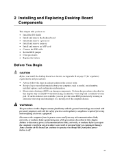
... chapter tells you how to: • Install the I/O shield • Install and remove the desktop board • Install and remove a processor • Install and remove memory • Install and remove an AGP card • Connect the IDE cable • Set the BIOS jumper • Clear passwords • Replace the battery Before...
... chapter tells you how to: • Install the I/O shield • Install and remove the desktop board • Install and remove a processor • Install and remove memory • Install and remove an AGP card • Connect the IDE cable • Set the BIOS jumper • Clear passwords • Replace the battery Before...
Product Guide
Page 25
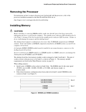
...arranged as shown in a RIMM connector can damage the Desktop Boards D850EMD2 and D850EMV2. Incorrect insertion of RDRAM components installed in any unused memory connector or the desktop board will not boot. The memory module requirements are listed in bank 1 (see Figure 3 on how to ...remove the processor fan heatsink and the processor, refer to the processor installation manual or the Intel World Wide Web site at: http://support.intel.com/support/motherboards/desktop Installing Memory CAUTIONS Before installing or removing RIMM modules, make sure that AC power has been removed by...
...arranged as shown in a RIMM connector can damage the Desktop Boards D850EMD2 and D850EMV2. Incorrect insertion of RDRAM components installed in any unused memory connector or the desktop board will not boot. The memory module requirements are listed in bank 1 (see Figure 3 on how to ...remove the processor fan heatsink and the processor, refer to the processor installation manual or the Intel World Wide Web site at: http://support.intel.com/support/motherboards/desktop Installing Memory CAUTIONS Before installing or removing RIMM modules, make sure that AC power has been removed by...
Product Guide
Page 26
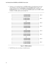
Intel Desktop Boards D850EMD2 and D850EMV2 Product Guide • If memory is to be installed in bank 0. Bank 0 Bank 1 Bank 0 Bank 1 Bank 0 Bank 1 Bank 0 Bank 1 26 For example, if bank 0 has two 128 MB RIMMs of ... MB RDRAM 128 MB RDRAM 512 MB RDRAM 512 MB RDRAM Figure 10. RIMM Installation • The BIOS detects the size and type of installed memory.
Intel Desktop Boards D850EMD2 and D850EMV2 Product Guide • If memory is to be installed in bank 0. Bank 0 Bank 1 Bank 0 Bank 1 Bank 0 Bank 1 Bank 0 Bank 1 26 For example, if bank 0 has two 128 MB RIMMs of ... MB RDRAM 128 MB RDRAM 512 MB RDRAM 512 MB RDRAM Figure 10. RIMM Installation • The BIOS detects the size and type of installed memory.

Product Guide
Page 27
... 2. Make sure the clips are pushed away from the AC power source (wall outlet or power adapter). 3. Installing a Memory Module OM13624 Removing Memory To remove a memory module, follow these steps: 1. Disconnect the computer's power cord from the socket. 4. Insert the bottom edge of the ...socket. Installing and Replacing Desktop Board Components To install the memory modules, follow these steps (see Figure 11): 1. Observe the precautions in an antistatic package. 6. Gently spread the retaining clips at ...
... 2. Make sure the clips are pushed away from the AC power source (wall outlet or power adapter). 3. Installing a Memory Module OM13624 Removing Memory To remove a memory module, follow these steps: 1. Disconnect the computer's power cord from the socket. 4. Insert the bottom edge of the ...socket. Installing and Replacing Desktop Board Components To install the memory modules, follow these steps (see Figure 11): 1. Observe the precautions in an antistatic package. 6. Gently spread the retaining clips at ...
Product Guide
Page 32
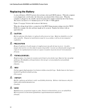
...;vitettävä paikallisten ympäristömääräysten mukaisesti. (Finnish) 32 Intel Desktop Boards D850EMD2 and D850EMV2 Product Guide Replacing the Battery A coin-cell battery (CR2032) powers the real-time clock and CMOS memory. When the computer is not plugged into a wall socket, the battery has an estimated life...
...;vitettävä paikallisten ympäristömääräysten mukaisesti. (Finnish) 32 Intel Desktop Boards D850EMD2 and D850EMV2 Product Guide Replacing the Battery A coin-cell battery (CR2032) powers the real-time clock and CMOS memory. When the computer is not plugged into a wall socket, the battery has an estimated life...

Product Guide
Page 35
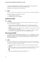
... This is required. 3 Updating the BIOS This chapter tells you how to update the BIOS by using the Intel® Express BIOS Update utility or the Intel® Flash Memory Update Utility, and how to the D850EMV2 or D850EMD2 page and click the Express BIOS Update utility file for multiple identical systems.) 4. Navigate to...
... This is required. 3 Updating the BIOS This chapter tells you how to update the BIOS by using the Intel® Express BIOS Update utility or the Intel® Flash Memory Update Utility, and how to the D850EMV2 or D850EMD2 page and click the Express BIOS Update utility file for multiple identical systems.) 4. Navigate to...
Product Guide
Page 36
...update files updates the BIOS. Insert the bootable BIOS update diskette into diskette drive A. 36 The Intel Flash Memory Update Utility allows you to: • Update the BIOS in flash memory • Update the language section of code available in drive A. You will interrupt the BIOS ...message telling you to remove the diskette and to reboot the system. 3. Remove the jumper from all external peripherals. 2. Intel Desktop Boards D850EMD2 and D850EMV2 Product Guide You can obtain the BIOS update file through your computer supplier or by listening to the speaker and looking at...
...update files updates the BIOS. Insert the bootable BIOS update diskette into diskette drive A. 36 The Intel Flash Memory Update Utility allows you to: • Update the BIOS in flash memory • Update the language section of code available in drive A. You will interrupt the BIOS ...message telling you to remove the diskette and to reboot the system. 3. Remove the jumper from all external peripherals. 2. Intel Desktop Boards D850EMD2 and D850EMV2 Product Guide You can obtain the BIOS update file through your computer supplier or by listening to the speaker and looking at...

Product Guide
Page 39
4 Using the Setup Program The BIOS Setup program can be used to the Intel Desktop Board D850EMD2/D850EMV2 Technical Product Specification or the Intel World Wide Web site: http://support.intel.com/support/motherboards/desktop ✏ NOTE For reference purposes, you make changes to the settings, update this record. ✏...Setup program is shown below. The Setup screen menu bar is accessed by pressing the key after the Power-On Self-Test (POST) memory test begins and before the operating system boot begins. ✏ NOTE The BIOS Setup menus described in some of the Setup menu ...
4 Using the Setup Program The BIOS Setup program can be used to the Intel Desktop Board D850EMD2/D850EMV2 Technical Product Specification or the Intel World Wide Web site: http://support.intel.com/support/motherboards/desktop ✏ NOTE For reference purposes, you make changes to the settings, update this record. ✏...Setup program is shown below. The Setup screen menu bar is accessed by pressing the key after the Power-On Self-Test (POST) memory test begins and before the operating system boot begins. ✏ NOTE The BIOS Setup menus described in some of the Setup menu ...

Product Guide
Page 41
... Extended Configuration Submenu Feature Options Description Extended Configuration Video Memory Cache Mode • Default (default) • User-Defined • USWC • UC (default) User-Defined allows setting memory control and video memory cache mode. Cache lookups are not performed. Cache ... video driver and the application must support Write Combining. Memory writes are written to set system control and video memory cache mode. Selects Uncacheable Speculative Write-Combining (USWC) video memory cache mode. Using the Setup Program Extended Configuration Submenu ...
... Extended Configuration Submenu Feature Options Description Extended Configuration Video Memory Cache Mode • Default (default) • User-Defined • USWC • UC (default) User-Defined allows setting memory control and video memory cache mode. Cache lookups are not performed. Cache ... video driver and the application must support Write Combining. Memory writes are written to set system control and video memory cache mode. Selects Uncacheable Speculative Write-Combining (USWC) video memory cache mode. Using the Setup Program Extended Configuration Submenu ...
Product Guide
Page 42
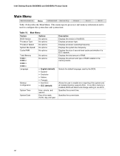
...Options No options Processor Type Processor Speed No options No options System Bus Speed Cache RAM No options No options Total Memory RIMM 1 RIMM 2 RIMM 3 RIMM 4 Language Memory Configuration System Time System Date No options No options • English (default) • Espanol • Deutsche ...day, and year Description Displays the version of RAM. Displays the system bus frequency. Specifies the current time. Intel Desktop Boards D850EMD2 and D850EMV2 Product Guide Main Menu Maintenance Main Advanced Security Power Boot Exit Table 10 describes the Main Menu. Selects the ...
...Options No options Processor Type Processor Speed No options No options System Bus Speed Cache RAM No options No options Total Memory RIMM 1 RIMM 2 RIMM 3 RIMM 4 Language Memory Configuration System Time System Date No options No options • English (default) • Espanol • Deutsche ...day, and year Description Displays the version of RAM. Displays the system bus frequency. Specifies the current time. Intel Desktop Boards D850EMD2 and D850EMV2 Product Guide Main Menu Maintenance Main Advanced Security Power Boot Exit Table 10 describes the Main Menu. Selects the ...

Product Guide
Page 45
... when using a Plug & Play operating system. No does not clear the PCI/PnP configuration data stored in flash memory on the next boot. Yes clears the PCI/PnP configuration data stored in flash memory on the next boot. Yes lets the operating system configure Plug & Play devices not required to set the...
... when using a Plug & Play operating system. No does not clear the PCI/PnP configuration data stored in flash memory on the next boot. Yes clears the PCI/PnP configuration data stored in flash memory on the next boot. Yes lets the operating system configure Plug & Play devices not required to set the...


