
Technical Product Specification
Page 78
... to PIO Mode 3 or 4, depending on the same IDE cable as an ATAPI master device. Intel Desktop Board D848PMB Technical Product Specification 3.3 Resource Configuration 3.3.1 PCI Autoconfiguration The BIOS can override the auto-configuration options by specifying manual configuration in the BIOS Setup program. The IDE interface supports hard drives up the two PCI...
... to PIO Mode 3 or 4, depending on the same IDE cable as an ATAPI master device. Intel Desktop Board D848PMB Technical Product Specification 3.3 Resource Configuration 3.3.1 PCI Autoconfiguration The BIOS can override the auto-configuration options by specifying manual configuration in the BIOS Setup program. The IDE interface supports hard drives up the two PCI...
Technical Product Specification
Page 80
...: US English, German, Italian, French, and Spanish. The default language is US English, which requires creation of a boot diskette and manual rebooting of the BIOS. • Updating replaceable BIOS modules, such as the video BIOS module. • Inserting a custom splash screen.... ✏ NOTE Review the instructions distributed with the upgrade utility before attempting a BIOS update. Intel Desktop Board D848PMB Technical Product Specification To install an operating system that supports USB, verify that the updated BIOS matches the target system to ...
...: US English, German, Italian, French, and Spanish. The default language is US English, which requires creation of a boot diskette and manual rebooting of the BIOS. • Updating replaceable BIOS modules, such as the video BIOS module. • Inserting a custom splash screen.... ✏ NOTE Review the instructions distributed with the upgrade utility before attempting a BIOS update. Intel Desktop Board D848PMB Technical Product Specification To install an operating system that supports USB, verify that the updated BIOS matches the target system to ...
Technical Product Specification
Page 91
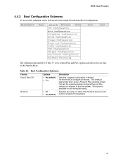
Boot Configuration Submenu Feature Plug & Play O/S Numlock Options • No (default) • Yes • Off • On (default) Description Specifies if manual configuration is appropriate when using a Plug and Play operating system. This option is for use during lab testing. Table 53. This setting is desired. No ...
Boot Configuration Submenu Feature Plug & Play O/S Numlock Options • No (default) • Yes • Off • On (default) Description Specifies if manual configuration is appropriate when using a Plug and Play operating system. This option is for use during lab testing. Table 53. This setting is desired. No ...
Technical Product Specification
Page 103
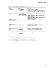
...Latency (Note 4) SDRAM RAS# to tRAS. Auto = Timings will be programmed according to address a column in two consecutive common clocks. Manual - Selects the length of detected SDRAM settings. This option is displayed only if the installed processor has a 533 MHz system bus. 3. Aggressive ...• Manual - This feature is displayed only if Extended Configuration is set to User Defined. 2. Aggressive = Selects most aggressive user-defined timings...
...Latency (Note 4) SDRAM RAS# to tRAS. Auto = Timings will be programmed according to address a column in two consecutive common clocks. Manual - Selects the length of detected SDRAM settings. This option is displayed only if the installed processor has a 533 MHz system bus. 3. Aggressive ...• Manual - This feature is displayed only if Extended Configuration is set to User Defined. 2. Aggressive = Selects most aggressive user-defined timings...
Product Guide
Page 3
... call attention to update the BIOS. • 4 Using the BIOS Setup Program: contents of data. It is intended for Intel® Desktop Board D848PMB. Conventions The following conventions are used in this manual: WARNING Warnings indicate conditions that, if not observed, can cause personal injury. Information Layout The chapters in this Product Guide...
... call attention to update the BIOS. • 4 Using the BIOS Setup Program: contents of data. It is intended for Intel® Desktop Board D848PMB. Conventions The following conventions are used in this manual: WARNING Warnings indicate conditions that, if not observed, can cause personal injury. Information Layout The chapters in this Product Guide...
Product Guide
Page 14
... to the desktop board and/or power supply. Related Links: Go to the following link or sections in this manual for: • The latest information on supported Intel processors for Desktop Board D848PMB http://support.intel.com/support/motherboards/desktop/ • Instructions on installing or upgrading the processor, page 28 in Table 4. Supported Processors...
... to the desktop board and/or power supply. Related Links: Go to the following link or sections in this manual for: • The latest information on supported Intel processors for Desktop Board D848PMB http://support.intel.com/support/motherboards/desktop/ • Instructions on installing or upgrading the processor, page 28 in Table 4. Supported Processors...
Product Guide
Page 15
...If your memory modules do not support SPD, you will see a notification to this manual for normal operation. Desktop Board Features Main Memory NOTE To be fully compliant with all applicable Intel® SDRAM memory specifications, the board should be populated with gold-plated contacts. •...ECC memory will attempt to configure the memory controller for : • The latest list of tested memory, http://support.intel.com/support/motherboards/desktop/ • SDRAM specifications, http://www.intel.com/technology/memory/pcsdram/spec/ • Installing memory, page 30 in Chapter 2 15
...If your memory modules do not support SPD, you will see a notification to this manual for normal operation. Desktop Board Features Main Memory NOTE To be fully compliant with all applicable Intel® SDRAM memory specifications, the board should be populated with gold-plated contacts. •...ECC memory will attempt to configure the memory controller for : • The latest list of tested memory, http://support.intel.com/support/motherboards/desktop/ • SDRAM specifications, http://www.intel.com/technology/memory/pcsdram/spec/ • Installing memory, page 30 in Chapter 2 15
Product Guide
Page 16
Intel Desktop Board D848PMB Product Guide Intel® 848P Chipset The Intel 848P chipset consists of the following devices: • Intel 82848P Memory Controller Hub (MCH) with AHA bus • Intel 82801EB I/O Controller Hub (ICH5) with AHA bus • Firmware Hub (FWH) Related Link: For more information about the Intel 848P chipset, go to: http://developer.intel... Related Links: Go to the following link or sections in this manual for more information about: • Audio drivers and utilities, http://support.intel.com/support/motherboards/desktop/ • Location of the internal audio ...
Intel Desktop Board D848PMB Product Guide Intel® 848P Chipset The Intel 848P chipset consists of the following devices: • Intel 82848P Memory Controller Hub (MCH) with AHA bus • Intel 82801EB I/O Controller Hub (ICH5) with AHA bus • Firmware Hub (FWH) Related Link: For more information about the Intel 848P chipset, go to: http://developer.intel... Related Links: Go to the following link or sections in this manual for more information about: • Audio drivers and utilities, http://support.intel.com/support/motherboards/desktop/ • Location of the internal audio ...
Product Guide
Page 19
.... The security feature uses a mechanical switch on the chassis that add-in the Firmware Hub. A supervisor password and a user password can be updated by specifying manual configuration in the BIOS automatically detects and configures the device for your computer, the PCI auto-configuration utility in the BIOS automatically detects and configures...
.... The security feature uses a mechanical switch on the chassis that add-in the Firmware Hub. A supervisor password and a user password can be updated by specifying manual configuration in the BIOS automatically detects and configures the device for your computer, the PCI auto-configuration utility in the BIOS automatically detects and configures...
Product Guide
Page 27
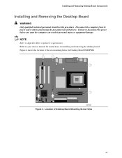
Refer to your chassis manual for regulatory requirements. OM16352 Figure 4. Figure 4 shows the location of Desktop Board Mounting Screw Holes 27 NOTE Refer to disconnect the power before performing the ... injury or equipment damage. Failure to Appendix B for instructions on installing and removing the desktop board. Location of the six mounting holes for Desktop Board D848PMB.
Refer to your chassis manual for regulatory requirements. OM16352 Figure 4. Figure 4 shows the location of Desktop Board Mounting Screw Holes 27 NOTE Refer to disconnect the power before performing the ... injury or equipment damage. Failure to Appendix B for instructions on installing and removing the desktop board. Location of the six mounting holes for Desktop Board D848PMB.
Product Guide
Page 28
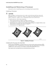
...Observe the precautions in "Before You Begin" on how to install the processor to the boxed processor manual or the Intel World Wide Web site at: http://support.intel.com/support/processors/pentium4/intnotes478.htm 28 Lower the lever to do so could damage the processor and ...the board. mPGA478B mPGA478B mPGA478B A Figure 5. Intel Desktop Board D848PMB Product Guide Installing and Removing a Processor Instructions on page 23. 2. the standby power LED should not be lit (see Figure 5). ...
...Observe the precautions in "Before You Begin" on how to install the processor to the boxed processor manual or the Intel World Wide Web site at: http://support.intel.com/support/processors/pentium4/intnotes478.htm 28 Lower the lever to do so could damage the processor and ...the board. mPGA478B mPGA478B mPGA478B A Figure 5. Intel Desktop Board D848PMB Product Guide Installing and Removing a Processor Instructions on page 23. 2. the standby power LED should not be lit (see Figure 5). ...
Product Guide
Page 29
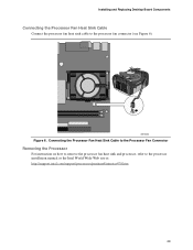
OM16353 Figure 6. Connecting the Processor Fan Heat Sink Cable to the Processor Fan Connector Removing the Processor For instruction on how to remove the processor fan heat sink and processor, refer to the processor fan connector (see Figure 6). Installing and Replacing Desktop Board Components Connecting the Processor Fan Heat Sink Cable Connect the processor fan heat sink cable to the processor installation manual or the Intel World Wide Web site at: http://support.intel.com/support/processors/pentium4/intnotes478.htm 29
OM16353 Figure 6. Connecting the Processor Fan Heat Sink Cable to the Processor Fan Connector Removing the Processor For instruction on how to remove the processor fan heat sink and processor, refer to the processor fan connector (see Figure 6). Installing and Replacing Desktop Board Components Connecting the Processor Fan Heat Sink Cable Connect the processor fan heat sink cable to the processor installation manual or the Intel World Wide Web site at: http://support.intel.com/support/processors/pentium4/intnotes478.htm 29
Product Guide
Page 56
... Submenu Feature Plug & Play O/S Numlock Options • No (default) • Yes • Off • On (default) Description Specifies if manual configuration is used to set the Plug & Play options and the power-on the numeric keypad of the Numlock key. Yes lets the operating system... in Table 16 is desired. Table 16. Specifies the power-on state of the Numlock feature on state of the keyboard. 56 Intel Desktop Board D848PMB Product Guide Boot Configuration Submenu Main Advanced Security Power Boot Exit Boot Configuration Plug & Play O/S Numlock [No] [On] Enter F1...
... Submenu Feature Plug & Play O/S Numlock Options • No (default) • Yes • Off • On (default) Description Specifies if manual configuration is used to set the Plug & Play options and the power-on the numeric keypad of the Numlock key. Yes lets the operating system... in Table 16 is desired. Table 16. Specifies the power-on state of the Numlock feature on state of the keyboard. 56 Intel Desktop Board D848PMB Product Guide Boot Configuration Submenu Main Advanced Security Power Boot Exit Boot Configuration Plug & Play O/S Numlock [No] [On] Enter F1...
Product Guide
Page 67
...333-320 MHz • Auto (default) • 266 MHz • 333 MHz • 400 MHz • Auto (default) • Manual - Manual - Controls Command Per Clock/1n rule mode. Selects length of time from read to tRCD. Selects the number of detected memory frequency value. Allows ...; 8 (default) • 7 • 6 • 5 SDRAM CAS# Latency • 2.0 • 2.5 • 3.0 (default) SDRAM RAS# to tRAS, min. Manual - Auto allows timings to be programmed according to address a column in two consecutive common clocks. Selects the length of clock cycles required to the memory...
...333-320 MHz • Auto (default) • 266 MHz • 333 MHz • 400 MHz • Auto (default) • Manual - Manual - Controls Command Per Clock/1n rule mode. Selects length of time from read to tRCD. Selects the number of detected memory frequency value. Allows ...; 8 (default) • 7 • 6 • 5 SDRAM CAS# Latency • 2.0 • 2.5 • 3.0 (default) SDRAM RAS# to tRAS, min. Manual - Auto allows timings to be programmed according to address a column in two consecutive common clocks. Selects the length of clock cycles required to the memory...


